I’m getting an error on this node for one set of solids and lines (but not others). The solid is more complex than the others and the lines more numerous but, outside of that, I don’t see much difference.
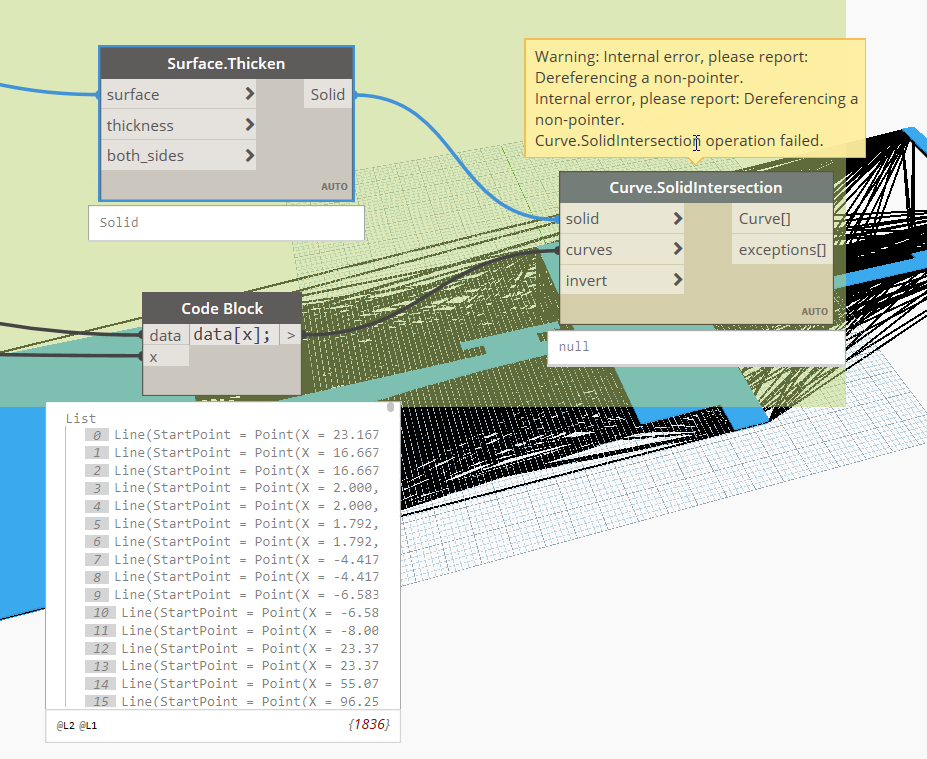

Thoughts? Did I break something? 
I’m getting an error on this node for one set of solids and lines (but not others). The solid is more complex than the others and the lines more numerous but, outside of that, I don’t see much difference.
Thoughts? Did I break something?
Might be a geometry scaling issue, or a geometry complexity issue.
Can you add the solid and a flat list of the curves into two Data.Remember nodes (install the latest version of Refinery to get this handy little wonder), and post a dyn with just the two remember nodes and the Curve.SolidIntersection node?
You’re on to something (naturally) but, while that fixes one problem, it pops up another. The intersect node works but on the wrong solid. With Geometry Scaling set to Medium I get this solid (from a Surface.ByPatch of a closed Polycurve);
But with Scaling set to Large it turns into this;
When I was looking at this before I had created the Surface/Solid from the endpoints of the polycurve which I think solved this problem but then I lose any curves so that’s no good.
I’m still downloading/installing 2020. When it’s done I’ll see about getting it up on the remember nodes.
Geometry scaling is the likely culprit. The geometry scaling settings I find really unhelpful though. Firstly you can’t set it in Dynamo Player, and secondly it’s possible that within the same script you’ll need two different scales. For example, collect all stairs in project (large), then get the treads (medium).
The best way I’ve found is to scale the geometry down manually in Dynamo and then run the intersection test. If it’s just yes/no result this is fine, otherwise if you need geometry you may need to scale it back up after.
And there’s no way to know if it needs to be scaled down before running it finding the problem I take it.
How do you scale it down and then back up in Dynamo? And by how much?
I would test first to see if the scaling is actually the problem. If so, I scale the 2 geometries by x0.001 from 0,0,0 reference. Check intersection and then scale x1000 from 0,0,0 to continue(if you need the geometry) But if you are in imperial you might want to change the values to something else. Too big is more of a problem than too small for intersections I found.
was thinking along similar line after the post – i’ll scale it down to see if it works, then i’ll know! lol
i suppose this could be part of the logic of the graph - work it with default values, if you get a null at key points pull those out into a sub-set of nodes to scale - work - scale, and then replace the nulls in the original and continue – pain in the rear but seems doable
Can you provide a data set to illustrate this? In theory when using feet medium scale should be able to accurately represent objects as small as a fraction of the thickness of a piece of paper as long as they are within a distance that is 1/3 the depth of the Marianas Trench from the origin.
Confirming the upper limit for geometry scaling is actually fairly easy. Find the minimum and maximum point for the bounding box for all elements, and create a vector from the origin to each of those points and get it’s length. Call that value D.
D < 100 then you can use small.D < 10000 then you can use medium.D < 1000000 then you can use large.D < 100000000 then you can use extra large.D > 100000000 then it’s time to step back and ask ‘why’ you’re using these units.In building scale units of measure (meters, feet), 100000000 is a fraction of the way around the globe. In a product scale unit of measure (say mm) it is 90% of the way across the English Channel. So either way if you have gone this far with your measurements then you will struggle with the curvature of the earth when you put down the tape, so best to rethink things.
For the ‘lower limit’ this is a bit harder to quantify, but I think something along the lines of the minimum distance between the simplest geometry primitives in use would do the trick - so the distance between points defining a curve, the radius value of a sphere, length of a line, etc. Once you have the ‘small’ number you know your lower bounds - call this one d.
d > 1 then you can use extra large.d < 1 then you can use large.d < 0.01 then you can use medium.d < 0.0001 then you can use small.d < 0.000001 then it’s time to step back and ask ‘why’ you’re using these units.At values less then 0.000001 you’re extremely optimistic about our understanding of the nature of distance. In building scale units (meters, feet) you’re talking measurements which are smaller then a fraction of a sheet of paper. Even in city scale units of measure (KM, miles) you’re returning something less then 2mm in size (exactly 1mm for KM).
I have started a chart illustrating selecting the correct working range, but need to do a bit more research before I share anything out. Hopefully this helps shed some light on things.
To be clear, the USA is about the only country that uses the Imperial system. The rest of the world use the metric system. Some countries, mostly European, use meters, Australia and the UK on the other hand use millimetres. This is convention which unfortunately Autodesk isn’t going to solve.
Estimating the geometry working range isn’t that useful because this needs to be calculated before running any Dynamo script, and still you need to open Dynamo to change any settings as it can’t be done via Dynamo Player.
Again it is not about accuracy or precision, but rather the limitations of Dynamo. I don’t really care (for 99% of the time) about the rounding precision. Most of the time it is simple things like getting the room boundaries and/or checking for intersections. While Dynamo COULD calculate some of these things at a particular Working Range albeit less accurately, it often throws an exception prompting you to change the settings. So again, if you are switching from the macro to the micro in the same script, this isn’t possible.
So at extra large working range (assuming you’re not using any decimals in your measurements because you are in mm), you still have geometry issues? Not trying to be combative here, just curious to see what is creating the issue and how it could be worked around or coded through.
At extra large, with no decimals, you should be able to work with 1mm to 100km geometries, right?
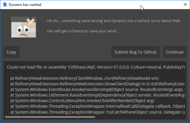
Something is off with my Refinery install. I get this when attempting to start it.
![]()
What Revit build are you on, and what version of Refinery did you launch?
Revit - 20.0.0.377 – 20190327_2315(x64)
Refinery - v0.9.4
Looks like the default package location needs to be at the top of the Manage Node and Package Paths for it to work. When I first did that (without restarting Dynamo) Refinery was in the View menu but after I restarted it moved to the toolbar so I’m in now. But I’m getting Host Issues about the DYFs being saved outside of the default folder. So for Refinery you can’t have nodes stored outside of AppData?
I haven’t tested this setup so I am not certain. Had a power outage and just getting back up and running, so let me try and get back to you.
Wait, all you need is a DYN of the remember nodes, yes? Not for it to actually be in Refinery I take it.
I added the remember nodes, ran the graph, and then deleted everything but the remember nodes to save this DYN. If that’s not the correct process let me know.
Rember Nodes.dyn (2.1 MB)
Here is an example of what I am talking about - it just came up again in another project. I’ll upload a dataset shortly so you can test.
Run on Small geometry working range I get an error:
Warning: Your inputs lie outside of the allowable modeling range, consider choosing the Small setting with a modeling range between 1E-06 and 100 from the “Settings => Geometry Working Range” dialog
but the containment test works
Run on Medium geometry working range, no geometry scaling error but containment test then fails with this error:
Warning: Polygon.ContainmentTest operation failed.
Could not text containment for self-intersecting polygon : –
Units are Feet and fractional inches
Can you also clarify how the Geometry Working Range settings is stored. Is it per Dynamo File, Revit session, Revit model?
Per DYN if I am not mistaken. You can double check by opening a nearly empty dyn in text editor and searching for scale.
On vacation with no plans to. It up the laptop until I return, but I’ll have a look then. Thanks for the example. ![]()
Just checked - yes Geometry working range looks to be saved per Dynamo file.


