Dear Dynamo aficionados
I am pleased to announce the release of BimorphNodes v3.0 available for download via the Dynamo Package Manager.
BimorphNodes v3.0 includes some major updates and a range of new nodes, including the new CADTextData.FromLayer node, which extracts text from a CAD link or import without exploding. Overview:
- Built on the Revit 2019 API with backwards compatibility up to Revit 2016 and Dynamo v1.2
- Major refactoring, performance enhancements and improved exception handling
- New CADTextData, LinkElement and CAD nodes
- Updates to existing nodes
- Full support for all Revit language versions
What’s New
BimorphNodes v3.0 is a major update with a focus on new nodes which include text extraction from CAD links or imports, bug fixes, multi-language support, speed enhancements, stability improvements and better exception handling. Continue reading for a detailed look at whats new:
CADTextData Nodes
New CADTextData nodes provide rapid extraction of text data from linked or imported CAD files in Revit. The node avoids exploding the CAD instance so it is not restricted to Revits 10,000 element limit. It means the days of pre-processing CAD files to isolate text for the purposes of exploding in Revit are over - simply link or import your CAD file and you can extract the text within seconds.
The CADTextData.FromLayers node also includes custom algorithms which work recursively to parse text entities from the CAD instance, enabling it to locate text in nested blocks regardless of the nested depth or any transformations. For example, if the text is in a block which is scaled, mirrored, and/or rotated, and it has nested blocks containing text which are also scaled, mirrored, and/or rotated, the node will compute all the transforms accordingly as it parses each nested depth.
The text is returned as CADTextData objects enabling you to decide how to use the data in your workflows. For example, the data can be used to create text notes in Revit (using the OOTB TextNote.ByLocation) or used for more advanced workflows involving geometry creation, such as extracting survey data to create toposurfaces:
Feature overview:
- Extracts all text entities from an input CAD link or import (ImportInstance’s)
- Avoids explode so there is no element limit and no need to pre-process your CAD file
- Works recursively to extract text data from any blocks with nested blocks to n-depth
- Supports all Revit documents and Families
- Supports all valid view types, including Section, Elevation, and Legend views
- Supports shared coordinates and rotations from true north
- Supports translated, scaled, mirrored and rotated Import Instances
- Dynamically adjusts units from the CAD file to your display units in Revit
- Provides nodes to query a wide range of text data attributes for maximum workflow flexibility, include the text value itself, insert point relative to your Revit coordinate space, and more
- Compatible with Dynamo Player
Action Nodes (methods) to obtain CADTextData instances:

Query Nodes (properties) for extracting attribute data from a CADTextData instance:

CAD Nodes
CAD.PointsFromCADLayers has been added to BimorphNodes enabling the collection and filtering of points from CAD links or imports. The node works much in the same way to the Curve-From-CAD-Layer nodes; input an Import Instance and leave the layerNames input unconnected to import from all layers, or input layer names as a list of strings to filter points from those layers.

CAD.SetLayerVisibility is also new and enables visibility control of specific layers for imported or linked CAD files in the input view.

LinkElement Nodes
LinkElement.ByRayBounce is a new collector node which takes a point and projects it to infinity. Any linked elements which intersect the ‘ray’ (the projected point), will be collected and returned as a Bimorph LinkElement. The node will return linked elements from any linked Revit file with optional inputs to filter elements by Category or only return the nearest element hit by the ray point. For convenience, the intersection point which hits the face of the element is also returned.

LinkElement.CopyToActiveDocument copies LinkElements into the active document. This method performs rehosting of elements where applicable and is designed primarily for model elements. Element binding is used to ensure that if you run the node multiple times (it might form part of a larger workflow), there are no risks of duplicates appearing every time your graph updates.
Note that not all elements are supported due to limitations in the Revit API, and due to the way Dynamo interacts with Revit, this node should only be used when Dynamo is in Manual execution mode, otherwise there is a risk of triggering a never-ending process.

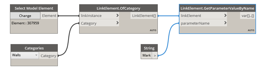
LinkElement.GetParameterValueByName gets the parameter value from a LinkElement and resolves the issue with the OOTB Element.GetParameterValueByName which only works with elements in the active document (parameter queries require the document object, which is invalid for linked elements). It works the same way as the OOTB node, but modified to work with linked elements.
LinkElement.Document is a new query node which returns the document object of the LinkElement.

Updates and Refactoring
The codebase for BimorphNodes v3.0 has had a major refactoring to aid maintenance and enhance performance. These changes are all internal, so you will not notice any differences if you already use BimorphNodes - just faster and more reliable performance. There have also been a number of feature updates to existing nodes:
CAD.CurvesFromCADLayers
CAD.DetailCurvesFromCADLayers
CAD.SymbolicCurvesFromCADLayers
The above nodes have been refactored to improve performance by minimising boxing and unboxing of the various curve types.

CAD.ReportInstances has been refactored with new internal functionality which subscribes to Dynamo’s events handler, enabling automatic closure of external Revit documents when Dynamo is closed or you close your graph. This only applies if you are using the filePath input to open external files - it has no effect on your active Revit document. This new functionality resolves an issue reported by some users where external documents would remain open in the background because the close input was not set to true before closing the Dynamo file or when using Dynamo Player.

CAD.LayerNamesInUse has three new boolean outputs to support the new CAD.PointsFromCADLayers and CADTextData.FromLayers nodes: containsCurves, containsPoints, and containsText. These outputs can be used as Boolean masks with OOTB nodes such as List.FilterByBoolMask for workflows using any of the CAD or CADTextData nodes.

Element.IntersectsElement includes a new output named intersectsWith to help group clashing elements in a more intuitive fashion. Simply match the index from the intersectsWith list with the corresponding index of the Element list (the sublist index) to group the elements in setB which clash with A. Note that this new output is simply the elementSetA returned unmodified, so previous workflows which group elements using the indexes of the elementSetA input with those of the Element output (the clashing elements) remains valid – as mentioned, this new output has been added for convenience to make grouping of clash results more intuitive.


Element.IntersectsSolid has a new output named intersectsWith for the same reasons and it works in the same way if you want to group the clash results - match the index from the intersectsWith list with the corresponding index of the Element list to quickly establish the elements which intersect with each solid. Like the Element.IntersectsElement node, the intersectsWith output is simply the solids input returned unmodified, and serves to make grouping of clash results more intuitive. The only issue users might encounter with this update is the fact that the output ports have changed order. To understand the potential issue this may cause, see the ‘Before Upgrading’ section.


Sheet.Duplicate has been completely refactored with bug fixes, improved performance and better memory management and exception handling, particularly for workflows which attempt to duplicate the same sheet multiple times. Support for PDF imports on sheets has also been added for Revit 2020 users.

Multi-Language Support
In previous versions of BimorphNodes there were a number of internal legacy functions which used English text (strings) to perform certain operations. Typically these strings were used as look-ups to obtain parameter values from elements in the model. However, the dependency on English-specific queries caused exceptions to occur for our international users who were not using English-language versions of Revit.
In BimorphNodes 3.0 the string queries have either been replaced with robust look-ups using built-in queries in the Revit API which automatically localise to the Revit language, or removed completely so all languages are now supported.
Before Upgrading
Lets be honest - a major drawback of upgrading in-use packages is not knowing how it might affect your graphs, or if a breaking change has occurred between versions. We have good news: BimorphNodes users upgrading to v3.0 can do so without any concerns - there are no breaking changes.
It is built on the Revit 2019 API and includes built-in backwards compatibility to Revit 2016. If you are using older versions of Revit and see compatibility warnings in Dynamo’s Notifications manager, these warnings can be dismissed as BimorphNodes manages combability for you.

With that said, there is one minor issue to be aware of:
Element.IntersectsSolid outputs have been modified to improve its functionality (see Updates and Refactoring for more info). Consequently, the order of outputs has changed such that the exceptions output has moved from output 2 to 3. This change will only affect you if you have connected the exceptions output elsewhere your graph. If so, and you upgrade to BimorphNodes v3.0 please take note of the following and update your graphs as explained below:
Before upgrading:

After upgrading, the wire will remain at output 2 which will cause downstream exceptions. To resolve, manually reconnect the repositioned exceptions output to any recieving nodes:

Subscribe for Updates
If you want user guides or would like to receive updates and news for BimorphNodes, subscribe to our YouTube Chanel, follow us on LinkedIn, or register for our newsletter at Bimorph.com:
BimorphNodes Dictionary
YouTube Channel
LinkedIn Company Page


 Feel like I come up with the most bizarre solutions to something that can probably be done easy
