I’m designing a script to automatically route conduits on a cable tray from one list of starting points to a list of ending points. I have already designed and gotten a shortest path algorithm to work. I have also made some implementations that allow for multiple conduits to run within the same cable tray, as long as the conduits are shifted across an axis. However, everything that I’ve done so far for shifting has been done manually.
I know that my output of the shortest paths for three conduit runs are given as three polycurves/three sublists of lines. I’d like to see if there’s some sort of way to use the ID of the sublist, or the positions of the lines to figure out which direction to shift the conduits such that they are not overlapping. Any advice for where to start with this would be greatly appreciated.
This problem is more complex than first meets the eye. Perhaps you could start by using your cable tray to create some, spaced out, cuboids to determine how many cables are residing per, lets say, meter. Also, some screenshots would also be helpful in understanding your issue to its’ full extent.
PS: I would keep the script which places the conduits seperate from the one that moves them afterwards.
Thanks for the response. Let me clarify a few things. The two scripts are supposed to be a part of one larger script (like subscripts). The line of logic in my web of nodes follows something like this (Get Cable Tray System → Create Mirror of it in Dynamo → Analyze Start/Endpoints and Compare to CT System modeled as a Graph → Create Shortest Path → (to be added: perform offsetting as necessary) → Display Cables.
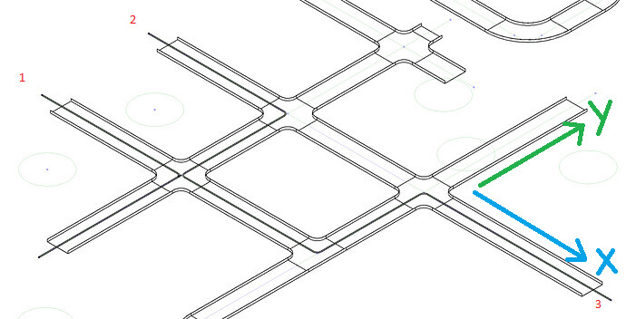
Here is a manually created (manually offset the overlaid cables) image of what I want a possible final output to be.
Cables always created on centrelines, and must be translated (+x, -x, +y or -y) according to where the next cable in their path is
Elbow.ByMEPCurves creates fittings for the cables however it likes (seemingly no way to control it, unless I split up the three paths, which I’m not sure how to do)
I don’t think I can help you here. I’ve thought about it but I wouldn’t know how to approach this myself.
Also, what would happen in a situation like this?
I haven’t thought about it yet, and to be honest, I think I would have to let them cross for now until I can get the conduit offset to work at a basic level.
Also, do you suggest I bump this post so more people see it? If so, how would I do that?
I would suggest starting with one of the pathing nodes like ShortestWalk (LunchBox) or PathOfTravel (Core). You should just have to define your tray “grid” and then sources and targets for each conduit run.
Oh, I’ve already implemented an algorithm for calculating the shortest path, if this is what you mean. As mentioned above, this is the general line of logic my web of nodes follows: Get Cable Tray System → Create Mirror of it in Dynamo → Analyze Start/Endpoints and Compare to CT System modeled as a Graph → Create Shortest Path → (to be added: perform offsetting as necessary) → Display Cables.
I am trying to add that offsetting section, with everything else pretty much complete (unless the offsetting section requires me to make a change in one of them).
Gotcha. I was just look at your second image and the issue with the fittings, but maybe that’s a separate topic.
When it comes to conduit “order” in terms of local position based on the number of conduits in a give tray segment… I think you have to look at the relative X and Y coordinates of where the conduit is coming from.
For example: If Conduit 1, 2, and 3 all have the same endpoint running in the Y direction then we need to determine their X offsets within the tray. 1 and 2 come from the left while 3 comes from the right. So we can easily determine then that 1 and 2 would offset to the left and 3 would offset to the right. Now we have to determine where to the left 1 and 2 would offset since we’re dealing with more than one. Additional conduits would always (as far as I’m aware) join from the outside. So the furthest conduit would exist on the inside before a nearer conduit would join it from the outside. In this case, Conduit 2 is the “furthest” along our Y direction so it would be first and Conduit 1 would join from the outside.
That’s how I see it working anyway. Obviously that’s a bit of a simplified explanation, but I think you can build the general logic with something like that.