Good afternoon people,
Can you tell me if it is possible to insert a block within an area, have this block follow the slopes of the surface and then indicate the slope of each block, similar to the video below.
Good afternoon people,
Can you tell me if it is possible to insert a block within an area, have this block follow the slopes of the surface and then indicate the slope of each block, similar to the video below.
Hi
Do you have a website for the original video on YouTube?
Can you attach an example drawing?
Hi
I have the same question of"eduardoolimot", I want to align a block to a surface in Civil3D
Thanks to everyone
Hi @eduardoolimot @energycivil3d1,
You can get the surface slope between 2 given points with a slope surface label.
Something similar to the video can be achieved by placing these labels on the surface . You will need a list of start points and a list of end points.
You can also customize the slope surface label style to show arrow and some element you wish like those aligned rectangles (block). Label styles can also be set to represent slope values ranges.
Hi @JaLo
thanks for your answer, unfortunately, I don’t know very well Dynamo, but I understand the first part of your post with the slope label for the surface.
I didn’t understand (start point, end point, generate vector), can you explain it more easily?
Many thanks
@energycivil3d1 sure thing, I’m not an expert but I can share the little I know.
Dynamo generates graphs based on nodes, usually for earch node you will have inputs and outputs.
Going a little deeper on the apporach i sugested (not the only way to do this, maybe not the fastest)…the slope label you are looking to insert is linked to a Civil3D Surface and when you put it manually (directly into C3D, _AeccAddSurfaceSlopeLabel) it request 3 inputs: Surface, Type (one point or two point) and the point(s).
In order to control the direction of measurement, you need a two point label. Here are some nodes that allow you to create a surface slope:
These nodes are requiring very similar information as mentioned above;
A1) Surface
A2) Location (start point)
A3) Direction (end point)
B1) Surface
B2) Line (a line would be defined by startpoint+endpoint, or point+direction+length)
C2) Label style (which can help you with colors, arrows and blocks)
You can also set as inputs, values for ditection and length
By creating a mesh that covers your surface, you can create points a the intersections of a mesh, lets calll them start points.
*Note: dynamo objects and autocad/civil objects are not the same, you can have dynamo objects displayed on dynamo and nothing will be drawn on your ACAD/C3D window, although, there are nodes to draw objects from dynamo objects
Once you get here, generate the surface label slope basen on these lines and set the desired style. (value H over V, value%, colors, text style, etc)
On a further step, you can get the slope value from the nodes and set a style base on the slope value. For example you can set:
Style1= green=slope values from 0.5% to 2%
Style2= red=slope values from 2 to 5%
and so..
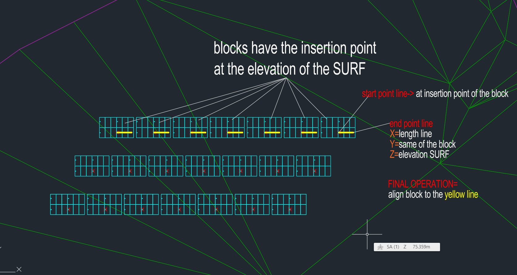
Many thanks for your reply you are very kind, I attached an image to explain workflow, because I don’t understand in your workflow how to align the SOLID
maybe I can draw the line, but I don’t know how to align the block to the line
You can solve this by rotating your CoordinateSystem (CS) a desired angle (ang), which is between X axis and the line (vector) you already defined.
Set CS on each startpoint, rotate each CS on plane XY and ang.
Create your blockref by rotated CS.
Two nodes in sequence should help here: Curve.CoordinateSystemAtParameter > BlockReference .ByCoordinateSystem
Thanks for the help Jalo, it was inspiring for me.
I reached my target, I found a way to do the routine after many attempts.
My graph:
thanks for your help Jacob, I found another way, but I appreciated.