Hello,
I have “wiggly” 3d-Polylines (red) of which I’m creating “straightened” versions (green). This picture shows a top view;
It’s a 3d-polycurve, so all vertices have different z-values.
The next step would be to offset the straight version e.g. 1m to the left and to the right (yellow lines).
In Civil3d this could be done with the “_AeccOffsetFeature”-command.
Using the “PolyCurve.OffsetMany”-node without an input for “PlaneNormal” offsets the polycurve in the z-direction. I want to achieve an offset in the XY-direction and I don’t know what kind of input is necessary to achieve that. All examples I could find are for planar objects. I’m aware that I’ll have to define a plane but I’m just not getting it to work.
I’ve attached the documents - any help is highly appreciated!
PolyCurveOffsetMany.dwg (1.1 MB)
PolyCurveOffsetMany_dyn25.dyn (36.7 KB)
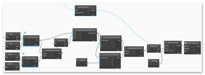
I got it to work with the rather messy approach of connecting the start- and endpoint of the line, creating a coordinate system along it and, using vectors, translating the geometry along the Y-axis of that coordinate system.
Feels a bit bloated and there’s definitely room for improvement but it gets the job done for now. I still havn’t figured out PolyCurve.OffsetMany.
PolyCurveOffsetMany_dyn25_v02.dyn (69.3 KB)
OffsetMany will make concentric curves around the base curve. You want to translate the curve. Instead of drawing a line using manual input points I recommend taking the first and last point of the PolyCurve using Curve.PointAtParameter with parameters of [0,1]. You can then use a Line.ByBestFitThroughPoints node, and a Curve.NormalAtParameter to pull the direction you want to move the curves.
Assuming you want to move this in plan, use a Vector.Scale node to remove the Z component, and then finally use a Geometry.Translate node with an input for direction and distance. The geometry is the original polycurve, the direction the vector, and the distance is [-1,1]*offsetDistsnce;.
1 Like


