Viewport Location Data Returns Wrong Results

I’m trying to place views on to sheets and get their location data. However, the results returned were obviously offset. (See figure below)

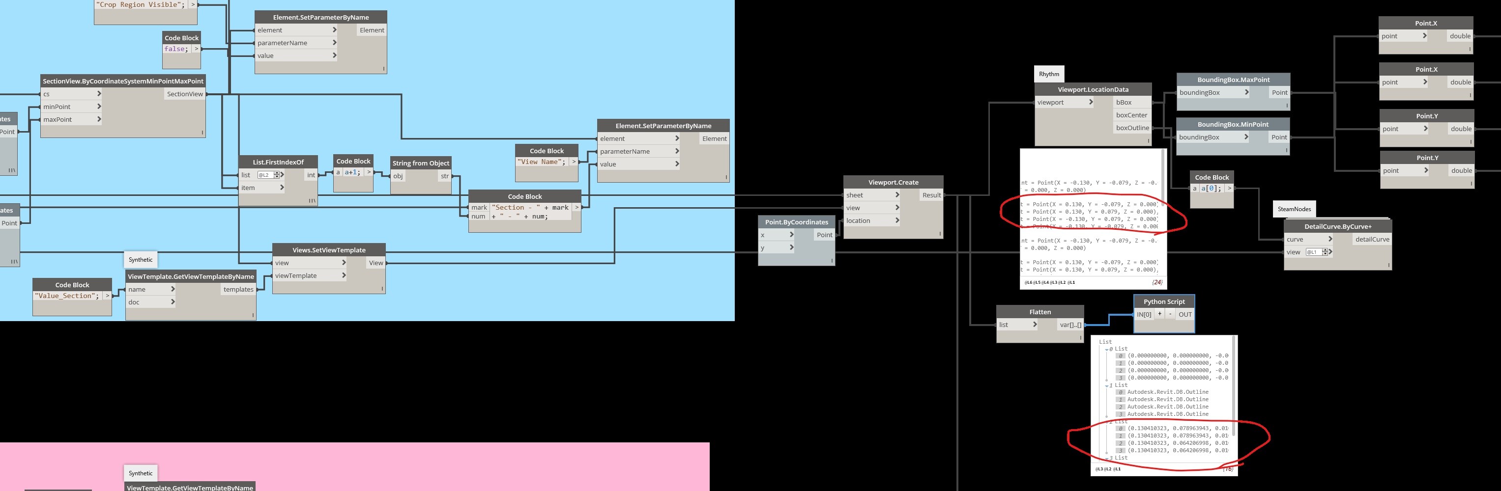
I placed the viewport at (0,0) but it was offset, and the outline (on the left corner) was not the right size. I tried the Viewport.LocationData node from Rythm, as well as write Python script myself, but they returned the same result…
Anyone, PLEASE help me with why it’s happening and how I can get it corrected! THANKS!!!

Janet

Here is the Nodes and the Python script I wrote.

import clr

clr.AddReference('RevitAPI')
from Autodesk.Revit.DB import *
from Autodesk.Revit.DB.Structure import *

clr.AddReference('RevitAPIUI')
from Autodesk.Revit.UI import *

clr.AddReference('System')
from System.Collections.Generic import List

clr.AddReference('RevitNodes')
import Revit
clr.ImportExtensions(Revit.GeometryConversion)
clr.ImportExtensions(Revit.Elements)

clr.AddReference('RevitServices')
import RevitServices
from RevitServices.Persistence import DocumentManager
from RevitServices.Transactions import TransactionManager

doc = DocumentManager.Instance.CurrentDBDocument
uidoc=DocumentManager.Instance.CurrentUIApplication.ActiveUIDocument

viewport = UnwrapElement(IN[0])

TransactionManager.Instance.EnsureInTransaction(doc)
outline = []
min = []
max = []
center = []
for vp in viewport:
	center.append(vp.GetBoxCenter())
	ol = vp.GetBoxOutline()
	outline.append(ol)
	max.append(ol.MaximumPoint)
	min.append(ol.MinimumPoint)
	
TransactionManager.Instance.TransactionTaskDone()
OUT = [center,outline,max,min]

Is the outline sample intended to be a detail line that bounds the viewport?

As for the Viewport being offset, a few possibilities:

  • Is the titleblock on the sheet offset?
  • Is the titleblock family offset from the family origin point?
  • Does the viewport have some out-of-bound annotation elements that might be disrupting the placement?

Hi Robert,
Thank you for your reply!

I am pretty sure that the title block is in the right position since I have other viewports (elevations views) on the same sheets that at the right position and with the right outlines.

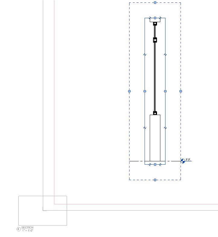
The section views were created by Dynamo with bounding boxes, which should have no annotation. I also preset the annotation crop of these views.

I am confused that the outline is not the same as the viewport shape. Very weird…

@Janet_W I worked with VP placement few months back and this is what I can recall:

  • If you place a viewport at (0,0) it means you are placing that VP’s center at the bottom left corner of the Titleblock.
  • The size that you get is not of the crop region but of the annotation crop or something like that.
2 Likes

Hi Amol,

Thank you for your reply!

That was my purpose to place the viewport at the bottom left corner. I have later nodes calculate the final position and move the viewport to it.
The current problem is that the center is not at the real center of the viewport. And it seems that the outline fits neither its crop region nor the annotation crop…

1 Like

@Janet_W The outline that you are getting is the one that encompasses the whole view (crop boundary + level/grid extensions)

But if you just want the cropbox boundary I would suggest you do this:
Get view’s Boundingbox > Get Length and Width > Divide them by View’s Scale

See if this helps

Note: Ignore the group names since they are from a different workflow

Hi Amol,

Thank you so much for your help!

The project I’m working on has no grids or anything else. It just has a wall and two windows on it. I tried your solution to get the view size. But I still can’t get the correct viewport center to relocate the viewport on the sheet.

I currently find a detour solution – Instead of directly citing the section view in the same .dyn file, I used “select” to get views and place them on sheets in separate .dyn file… and it works.
There might be something wrong with the dataflow from my “SectionView.ByCoordinateSystemMinPointMaxPoint” node.

Thank you again for your help!

– Janet

1 Like