I am using Revit Structure and need the footings to pull the “Column location mark” parameter from the column elements.
In Revit a column will know it’s “column location mark” based on the grids that are intersecting. However the footings do not do this. I was hoping Dynamo could somehow look at the shared location of the column and extract either the intersecting grid information and or the column location mark.
Any thoughts if this could be done? I want to tell a contractor at grid A1 we require a specific footing.
Is your footings placed below columns? One of the possible ways to extract column location is to use “Element.Location” from clockwork package. I am not sure if i understand you properly possible for any screenshots?
This is an interesting question. Structural Columns have a property called “Column Location Mark”. Structural Isolated Foundations do not have this property. So, I think what Bill_Wright is trying to do is get that same property to Foundations. The actual grid location for a specific footing location.
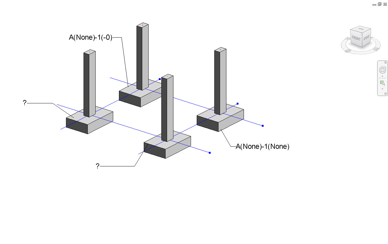
@Bill_Wright@Tom_Kunsman In that case one of the possible way is to go for Geometry approach.Create Parameter called “Footing Location Mark”. Extract geometry for footings and for grids curves->Geometry.DoesIntersects->Filter.BoolMask grids which intersects with footings. Below is the process in action:
This graph is made to work for any element with a point location. It calculates the distance from the nearest grid if it’s not in a grid intersection (just like the column location mark)
@Einar_Raknes Looks like @Bill_Wright is having issue in clockwork package. It doesn’t read the values. @Bill_Wright are you getting “null” or “Empty List” when you connect to “Element.Location” node?
Can you show us the values of “Element.Location”?
This is a pretty interesting use of Dynamo. I’m assuming you had to made a custom footing tag to read the new data you attached? I’d love to see what a final sheet looks like, out of shear curousity, since it seems like you’re implimenting it in a sweet iso view in addition to attaching this new info to the foundation elements.
thank you for the comments. I really like the use of Dynamo for this application. Currently, the script places the grid intersection in the comments field and we have the footing tag looking at that parameter. However, you could quickly create a custom shared parameter for the footing and create the tag as you mentioned.
The 3D view was really just a mock project file and I thought it would be cleaner to see. The main application for this workflow is so that the contractor sees a footing schedule based on grid location and not based on Footing name like F1,F2,F3. If we tag footings F1 etc in plan view the contractor now has to go to the schedule and find the size information. For this purpose our footing schedule the contractor sees at grid A1 all the information for that footing. We find it easier for the contractor and more clear for the drawings.
Thanks for sharing your thoughts. Continuing to go a bit off topic: that’s a very interesting approuch to scheduling. We’re still using F2, F3 etc in our shop (pruely by convention) but I’m always open minded to ways to make the information on production drawings clearer to contractors and the trades. What jurisdiction are you in? In the office I’m known as a bit of a radical; previously I’ve advocated internally for the use of more 3D isometrics wnen encountering complex structural conditions (hence my follow up comment).
Must be a pretty big building to need something like this… Looks like fun @Bill_Wright
The new version of PRORUBIM has a different node for Grids.DivideByOrientation. The version in your example file has Port 1 as the input and output. The new node has grids as the input and hGrids & vGrids as two separate outputs. How can I make this file work with the new node format?
This topic is already solved and also it doesn’t match with your query. I will close this down, so if you have a more specific and Dynamo related question, please start a new thread. Thanks