Hello,
I am still a beginner on Revit (I use 2021) and I have a difficulty in making my PC circuits.
Indeed, it is rather tedious to make a good graphic representation because the wires of the circuit are systematically connected to the connectors of my PC. This means that for juxtaposed plugs, one cannot see anything.
The solution I was given is to move the geometric terminal node of each wire. It’s quite long.
I’m struggling to find a “quick” solution to this problem with Dynamo but I’m not sure where to start.
Do you have any ideas?
Here are some screenshots showing my problem.
What happens “naturally”:

What I would like to achieve:
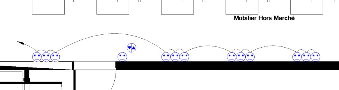
Thanks in advance for your advice