I am trying to get a polycurve from a pipe network in my Revit file. I could not find another way to get the centreline (as a polycurve) of this network other than following the below workflow.
However, there are two problems with the workflow when:
- The piping is not drawn at one go i.e. continuous element IDs of pipes are not there in Dynamo workflow and a polycurve could not be formed.
- joinTolerance (for the gaps between two pipes due to pipe fitting) is greater than a (short) pipe piece length.
Is there any other way I could get a clean polycurve without interruption/gaps so that I could utilize this polycurve to draw flex piping out of it?
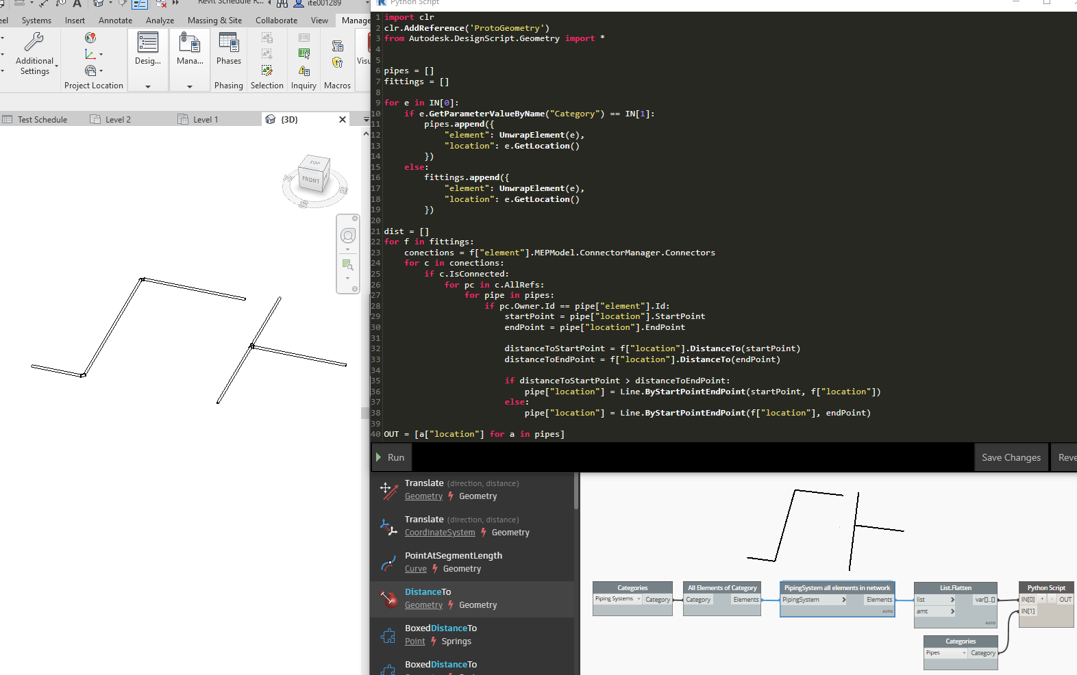
hi @theshysnail,
please take a look at the dynamo script below,
-biboy
3 Likes
Hi,
Thanks for the response. Let me check.
Could you please share the python script so that I could copy it?
Hi,
Piping Network Elements.dyn (10.8 KB)
attached is the dynamo file I used. please mark my comment a solution if solves your problem so that other user can verify/use the solution as well.
1 Like
Hi @theshysnail,
Just giving back to the community that makes our BIM life easy 
1 Like
Where did the Custom node. PipingSystem all elements in network come from as it does not load when i download and open the script.
Cheers.
Hi,
I guess, it’s from the MEPover package.
2 Likes
Do you have the same for his Duct?