Goal: Inventory stocks of a selected area should be dynamically added and updated in the model in the form of an inventory list.
Current setup:
- A test Excel file containing various component names and the number of times they should be placed within the designated area.
- The Excel list has already been filtered, so I know exactly how many components of a specific type need to be placed in the selected storage area (components stored in other areas are irrelevant!).
- Dimensions of the components to be placed (length and width; height is irrelevant for now).
- A fixed spacing that must be maintained between the objects.
Challenge:
I am wondering how to best place the objects within the area so that the total number of components is successfully placed. For a rectangular area, this task is relatively straightforward. However, the Dynamo script must also handle curved and multi-sided storage areas, ensuring that every object is fully placed within the boundaries.
What edge or reference line could I manually draw or select to organize the placement of objects systematically?Excel_Import_V4.dyn (171.8 KB)
Excel_Test_V1.xlsx (12.0 KB)
Where are you generating the placement in the graph? A screenshot would help.
My approach is as follows:
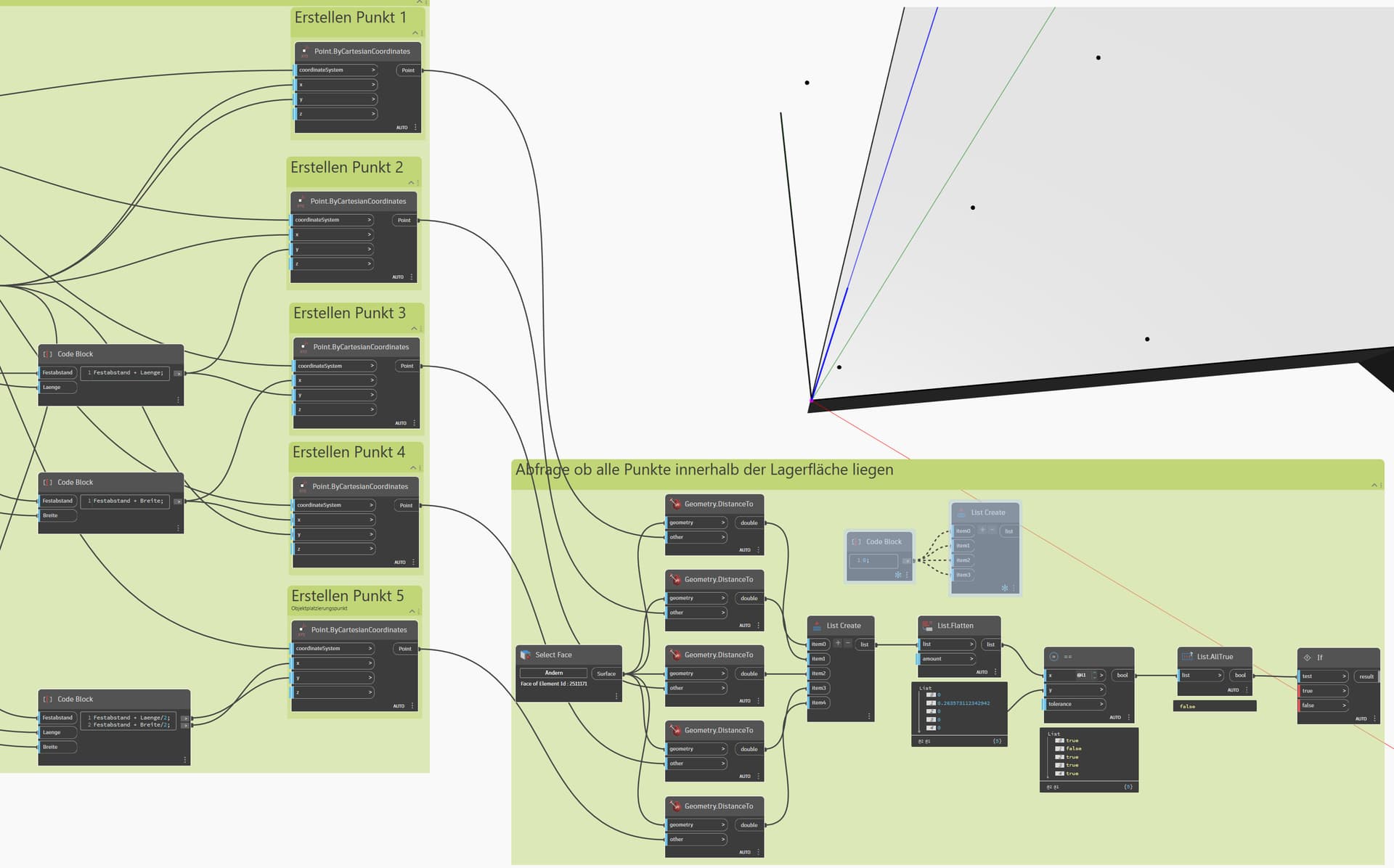
- The four outermost points of the objects to be placed are created (+ a fixed distance that is calculated so that the objects are later placed on the storage area with a uniform spacing).
- Then, it is checked whether all these corners lie on the surface → Distance to the surface = 0.
- The result should be either False or True.
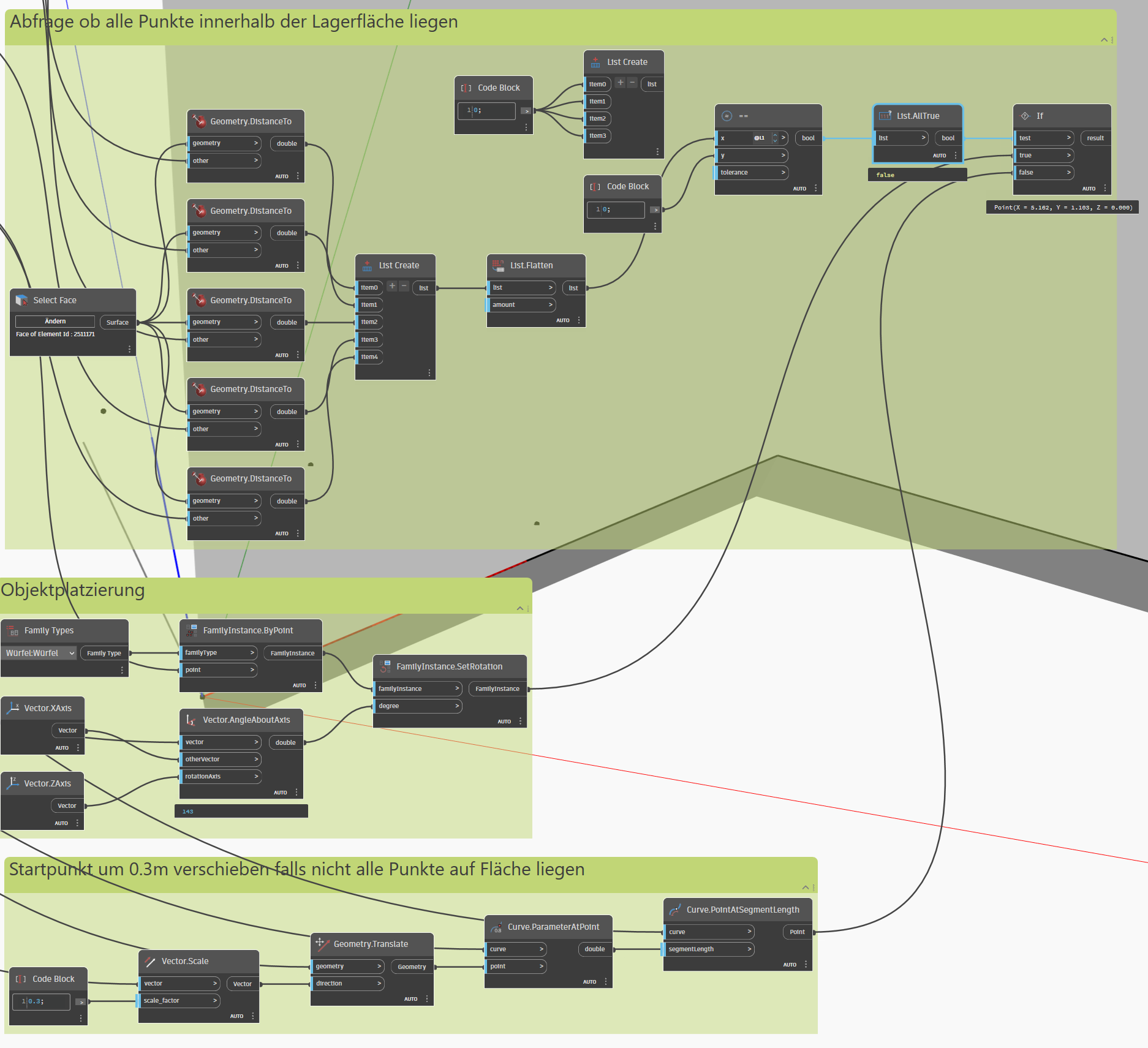
If the result is False, the placement should move forward by a fixed distance (e.g., 0.2) along the curve that guides the placement. Then, the points should be placed again.
If the result is True, the object should be placed at Point 5.
I think I need to solve this using the If Node, or should I do it directly with a Python script?
The problem with this script is that it places the object although not all points are on the surface.
The if node is just not doing the job for me I guess…
I think the job could get done by a while and if loop with python code but I never worked with python - maybe I have to learn it a bit to have a working code…
I recommend C# for this, but Python or some imperative design script and custom nodes can work as well. If nodes will struggle as once an object is placed you can’t use it a second time meaning you’d either have to place a set of nodes for each object or iterate over the shape making a modification over time.
Look into the using coordiante systems for placing the actual geometry of the object rather than points, as well as testing containment via Geometry.DoesIntersect (Offsetting inwards oh so slightly can help there, either by PolyCurve.OffsetMany or Solid.ThinShell)
1 Like
Thank you for the detailed input ! I will have a look at C# and Python, since I have 0 experience with either of them, what would you suggest for a total beginner?
The problem with Geometry.DoesIntersect is that it’ll say the objects intersect but the cube in this example is not 100% on the surface, so this should not create a “true” result
I can’t see where the intersection is there, but in a 2D example where I’m working with surfaces I have two properties for each object - one for the object itself and one for the ‘clearances’. The clearances for objects which only need their own space are slightly inset - 0.01 units typically and if you’re working with sqm or sqft it’s negligable. You can then check if the occupied space intersects the clearance, and if so don’t place the object there. If it does’t you have a margin of error intersection at most.
The same concept applies to solids, but generating the inset solid takes a bit more Dynamo experience (still only takes 2 nodes though).
In the screenshot, the white area is the storage area where the objects (in this case, the gray cube) are supposed to be placed. The cube is partially on the surface but not entirely.
Therefore, I believe the Intersect Node is not helpful in this case, as it already considers a partial overlap as valid.
In the further course of the program, the cube in the screenshot should not be placed at all by the code. Instead, it should be shifted further to the right along the outer edge of the surface until the upper left corner of the cube is also on the surface.
I hope I explained it a bit clearer, it is quiet difficult for me to explain it in english and in text messages haha
You need to place objects based on coordinates inside the space but test it against geometry which represents where you can’t put things. So if you have to fit stuff in a floor you start the initial ‘invalid’ space is a small geometry that wraps the perimeter of the floor. if you have an opening in the middle of the floor you also put a small geometry to fill that.
Every time you place an object that object also needs to be added to the occupied geometry and removed from the available geometry. It’s a two part system.