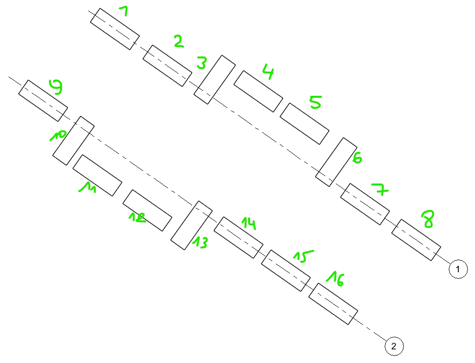
I’m trying to sort/order my elements in a list according to their placement in the XY coordinate system from top left to bottom right (so regardless of there ID or the order they were created/placed in). They are placed along a multi-segment grid and should be in the order as displayed:
Any suggestions are welcome, I’ve also attached a rvt-file with some elements to test with, the grids are not multi-segmented though… Also attached is the start of a script…
I used 2 different approaches for finding the center point of my elements, by creating a center point between the 2 adaptive points and by using Element.Location. Both seem to give different results…
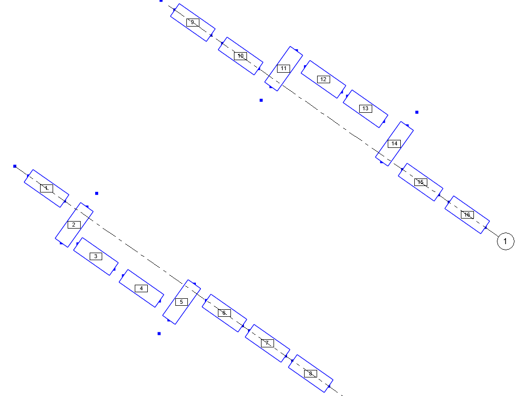
I’m writing the order value to the Mark-Parameter as an easy way to check if the list has the correct order…
The first part of the process for building an automation is to write down the sequence of operations you have to perform. So if you had a pen and paper in front of you with the grids and objects drawn, what would your steps be?
From there you’ll have a map showing you what you need to do and the order you need to do it in, which makes building the graph MUCH easier. Give it a shot and see where you get.
I’ve tried implementing those solutions but I can’t seem to get it working for my elements.
I think it’s because my elements are not perpendicular/orthogonal…
Maybe numbering by using a Spline works better in your case. There is also a ‘Pick in Order’ node
(i don’t know which Package). You get a List with the Element in the order you picked.
@bvs1982 can you elaborate on the Spline?
The ‘Pick in order’ will not be an option for me, since my actual model consists of more than 100 of these elements…
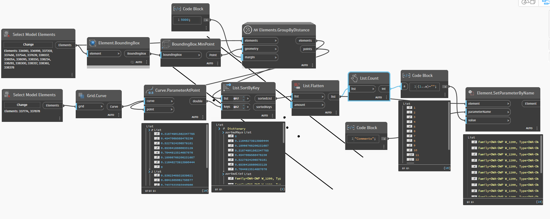
For each group:
A. Get the location of the element
B. Get the closest point on the associated grid.
C. Get the parameter of the grid at that point.
D. Sort the elements in the group by the parameters
Flatten the lists of sorted groups
Build a range of mark values as long as the flat list of groups
Set the mark values of the flattened list by the range of values
@jacob.small Sounds very promising but unfortunately I don’t have the time or brainpower left to attempt this right now. That’s why I posted on here with everything I was able to do.
Right now the suggestion of @sovitek kinda works for the most part and I will probably just fix those couple that aren’t right, manually for now. But I’ll have to take a look tomorrow if it also would work on my actual model/project.
Is there a way to get the element geometry by using regular nodes? I saw you used a custom node from your own package but’ I’m very limited in what packages I can use (company policy).