Hi
Im trying to create a dimension by extracting reference objects from model curves and appending them to a referenceArray . Anyone knows how could I extract references from model curves to include them inside the NewDimension function? Ive tried reading the documentation about reference objects but ive stil not found anything useful.Ive seen some genius loci packages to extract wall references, what if I wanted to only get references fom lines and walls without having to use external packges?
I would really appreciate any help,
Thanks!
new_dimension=doc.Create.NewDimension(doc.ActiveView, line, elements_ref)
line = UnwrapElement(IN[0]).GeometryCurve
#line=IN[0]
references=UnwrapElement(IN[1])
doc = DocumentManager.Instance.CurrentDBDocument

opt=Options()
opt.ComputeReferences = True
opt.IncludeNonVisibleObjects = True
opt.View = doc.ActiveView

elements_ref=ReferenceArray()


for element in references:
	elements_ref.Append(element.get_Geometry(opt))


TransactionManager.Instance.EnsureInTransaction(doc)

new_dimension=doc.Create.NewDimension(doc.ActiveView, line, elements_ref)

TransactionManager.Instance.TransactionTaskDone()
1 Like
so,
you are currently inputting referrences and you want to create that part yourself?
Roughly: elements have geometry en geometry has faces and faces are references.
But other parts react differently like gridlines, grids etc.
So I don’t think people can give you a simple answer: time to showcase your attempts and goal more clear.
1 Like
Hi , thanks for your answer!
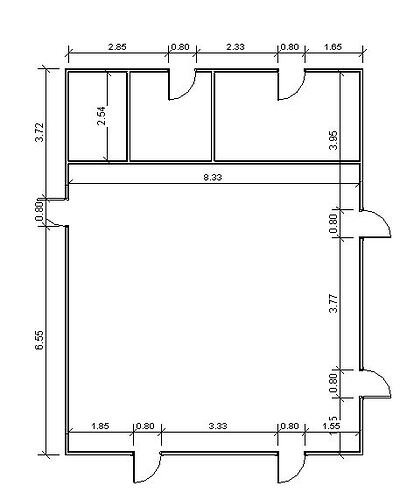
I wanted to get the modelcurves references since I have several intersecting walls that are not being annotated by my current dynamo python block. Would you happen to know how to get the references from intersecting walls ? and how to anotate not just the external face of the wall but also the interior one? Here is what Ive writte so far:
import sys
import clr
clr.AddReference('ProtoGeometry')
from Autodesk.DesignScript.Geometry import *

clr.AddReference('RevitAPI')
from Autodesk.Revit.DB import *

clr.AddReference('RevitNodes')
import Revit
clr.ImportExtensions(Revit.GeometryConversion)
clr.ImportExtensions(Revit.Elements)

clr.AddReference("RevitServices")
import RevitServices
from RevitServices.Persistence import DocumentManager
from RevitServices.Transactions import TransactionManager


line = UnwrapElement(IN[0]).GeometryCurve
#line=IN[0]
walls=UnwrapElement(IN[1])
doc = DocumentManager.Instance.CurrentDBDocument

def parallel(v1, v2):
    #gets two vectors and check if parallel
    return v1.CrossProduct(v2).IsAlmostEqualTo(XYZ(0, 0, 0))

opt=Options()
opt.ComputeReferences = True
opt.IncludeNonVisibleObjects = True
opt.View = doc.ActiveView
faces_arr=[]


def delete_dimensions():
	dimensions=FilteredElementCollector(doc).OfCategory(BuiltInCategory.OST_Dimensions).WhereElementIsNotElementType().ToElements()
	for dimension in dimensions:
		TransactionManager.Instance.EnsureInTransaction(doc)
		doc.Delete(dimension.Id)
		TransactionManager.Instance.TransactionTaskDone()


def create_dimensions():
	delete_dimensions()
	walls_2=FilteredElementCollector(doc).OfCategory(BuiltInCategory.OST_Walls).WhereElementIsNotElementType().ToElements()
	all_lines=[]
	for wall in walls_2:
		elements_ref=ReferenceArray()
		ln=wall.Location.Curve.CreateOffset(2,XYZ(0,0,1))

		all_lines.append(ln)
		for ref in wall.get_Geometry(opt):
			if isinstance(ref,Solid):
				for face in ref.Faces:
					if parallel(face.FaceNormal, ln.GetEndPoint(1) - ln.GetEndPoint(0)):
						elements_ref.Append(face.Reference)
As you can see , all the external faces of walls are being measured and annotated but some interior parts of the wall are not, also, intersecting faces are not being annotated.
2 Likes
That is already very clever. Could you show how it’s used in a graph or share the DYN?
Hi @mochilas.wayuu14,
Top of hat because too many deadlines atm.
I believe that
- a wall has faces (6: front back left right top bottom)
- an intersecting wall creates edges (2 vertical lines) which are added to the edge array
so your original wall will have
- 6 faces
- 14 edges
**12 original ones (the wall itself) (4 per face, divided by 2 due double count)
**2 of the intersecting wall.
