I am trying to generate and extract the center path of a surface generated by a room collected in revit.
You can see in the image below, that I’ve photoshoped, the red line that I’m trying to generate.
So far I failed to create that line in dynamo. Any ideas ?
To really nail down the best way to do this we need to know more of where you are and what you are trying to accomplish.
Example One: if you are doing a life safety travel path diagram it’s usually better to look at doors instead of rooms, and find the shortest path around the room between the doors, then offset those lines by 1/2 of the corridor width.
Example Two: if you are doing tributary areas for framing you want to offset the long lines by 1/2 of the distance to the line across the surface at the midpoint of the offset line.
Shed some more light on where you are and what you are after and we can help you got to the solution in the best way possible.
You’re right, I should have explained a little more about what I am trying to do through dynamo.
So, for a project I need to trace all the possible circulations (aquipments, wastes, visitors, workers, etc…) that I have in a very big building. So it’s kind of similar to a life safety travel path diagrams, but not quite, in the sense that I need all the possible circulation paths for each level and not just the shortest path to the nearest emergency exit.
I’ve look at differents dynamo scripts relative to safety travel path that are using doors to trace a path and it was a very good idea as you point out, but lines that are generated are way too “jaggy” to be use in a proper diagram. Maybe because of the use of a Delaunay Triangulation. And also, I’ve a lot of rooms that are bounded by Room Seperation Line but that’s another topic.
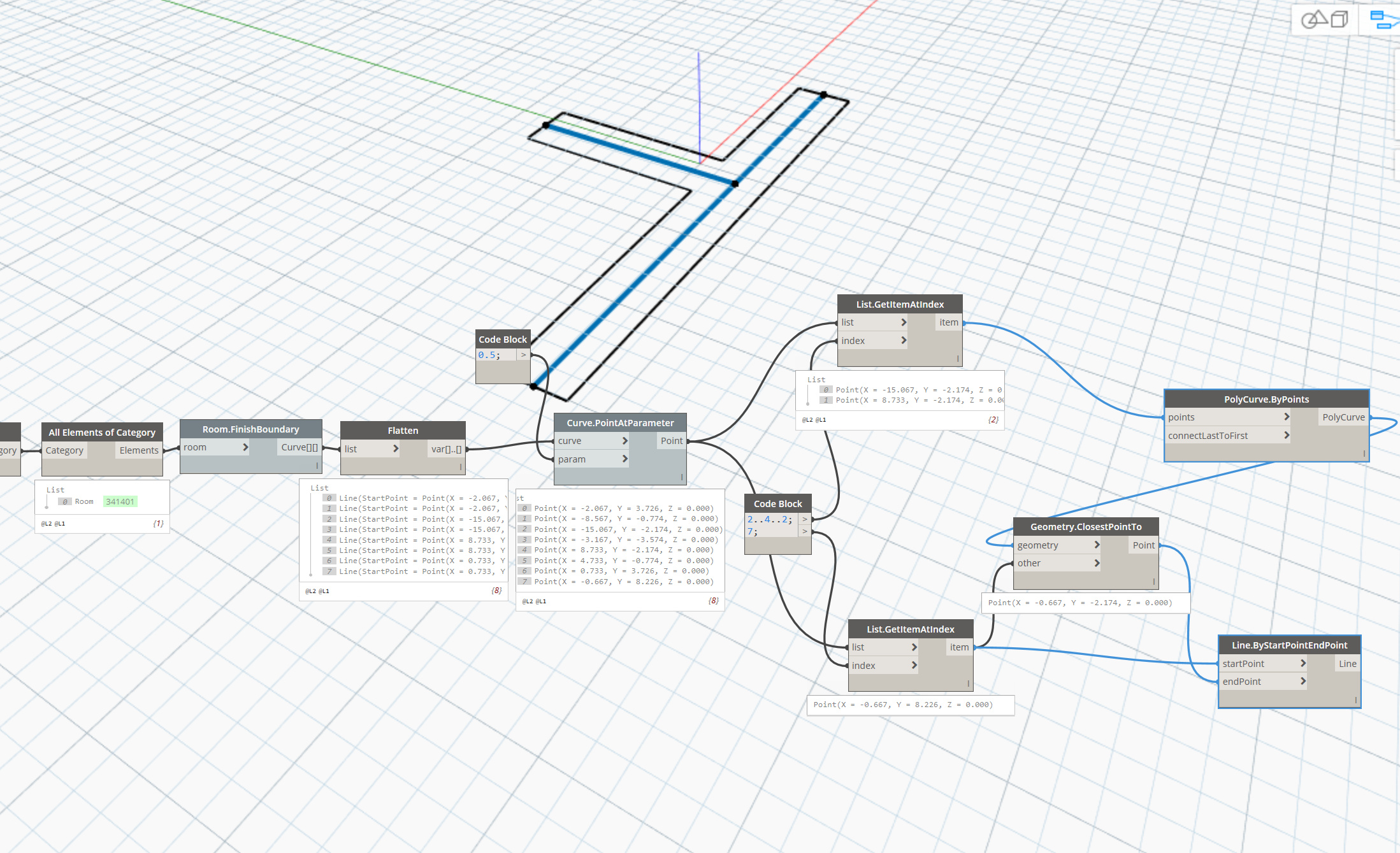
To sum up, all the process to identify rooms and doors are ok, even the part to connect a door to the center path of a surface is ok, thanks to Antoniorusconi and his “ClosestPointTo” node
But I’m still missing a good way to generate clean center path as in the exemple bellow :
And also, I’m not only looking for some kind of magical all-in-one solution that will generate everything automatically without any user input, if it’s semi-manual (for exemple if the user have to select a few lines or wall to trace that center path) it will already be a great improvement compare to my situation now.
This is a far greater undertaking than indicated. Best bet may be to find the width of the space and offset the longer lines by that distance but that fails to capture the vertical leg of the T in your presented option… can you provide a sample dataset so everyone can be sure we’re looking at the same data? Could even just be a sample corridor which you previously indicated and just a few of the connecting rooms as a start.
I have done some tests and came to something that could also be worth to share. I have isolated the corner points that were not at a corridor end and created lines from them to split the surface of the room. I thought that it would be easier to find the axis on such simple shapes, since they have only two short and two long sides. I used Intersection.GeometrySplit from Lunchbox for that:
Thomas_Mahon, the medial axis idea is very good! As you said it might be a way to find a solution that doesn’t depend on a certain configuration of a corridor. But I’ll need some time to wrap my head around this solution ^^. Especially when I read Roland Geraerts’s thesis found by JacobSmall. But globally, it’s the method used by Revit to automatically generate roofs !
First, the boundary curve is subdivided into many points
Then the 2d Voronoi is calculated for these points (because every Voronoi edge is equidistant to 2 or more points (which is the definition of the Medial Axis)
I can’t use the voronoi node that exist in dynamo because it’s based on a surface input and it seems that the methodology is always based on curves. Bad luck.
Also, maybe I’ll give a try to a semi-manual solution, and compare both results. I had in mind that I could manually draw all my major circulations with detail lines, and only try to automatize to link the door to it (maybe with a custom python node that will compare the facing orientation of my doors with my detail lines for finding parallelism and pick the closest point on the closest line). With some Intersect.All node and after removing duplicates it could work and give me all segment lines that I need. And already save me quite some work in a first time !
PS :Yna_Db, a methodology with corner points is a very good strategy, and I thought about trying to split each circulations to obtain more easy to use “boxes” but I don’t have any idea at all on how to achieve this with some degree of automatization. And if we have to handpick every single corner point I’m afraid it will be a rather fastidious work ^^. How to tell to Dynamo which points to isolate and to connect ?
I am not in front of this graph but I think that I have simply collected all points and subtracted those from the ends of corridors. It was not straightforward since comparing point coordinates may encounter inaccuracies issues…
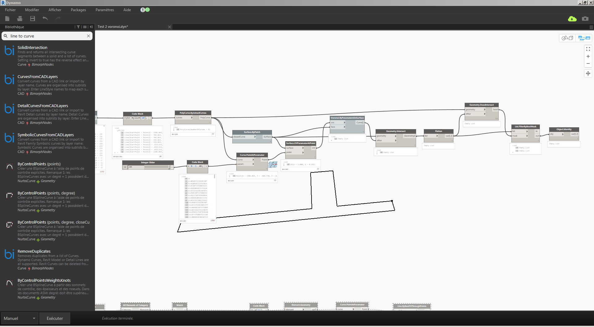
You can always build a surface from the curves and use it with the built-in voronoi node, it will just be a lot more inefficient than the rhino solution:
@Dimitar_Venkov, What Working Range are you using and about how big are your curves? Regardless of my Working Range and curve lengths I almost always get a Working Range error, even at Extra Large.
I ran the above on 1.21, working in mm. The equivalent geometric range should be the default one. I wouldn’t be surprised if the voronoi node fails in 1.3+ due to the introduction of the geometric ranges, there’s a off-plane verification for each voronoi vertex that need to happen at small decimal fractions. I’ll run some checks with 1.3.
Edit: Indeed, it seems like this does not work in 1.3+