I’m currently working on a new workflow that places a “floor” element underneath another element (generally pilecaps or ground beams) by selecting the bottom face of that element and forming the new floor with the same vertices.
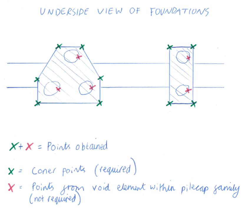
However, my problem is that the bottom face (of the element above) also returns additional points (not just the perimeter corners of the face. This is because there is a void cut element inside the pilecap families which is picked up as another vertex of the bottom face.
Therefore, my task is to take a list of vertices and automatically work out which of the points are the actual corner points.
I’ve tried to achieve this myself with no success and have tried complicated alternatives, also with no success. At the moment i’m not able to access Revit but the sketch below is an example of what i’m trying to achieve.
I am not sure how i should utilise the List.SortByKey + List.LastItem + Curve.StartPoint nodes.
I have however continued the workflow without these nodes and have a “solution” BUT it still throws out errors, so although the output seems right i’d be very apprechiative if you could take a look at the screenshot of the workflow to see if it’s blindingly obvious where it’s all going wrong
I’ve had a look over it myself and i can see that it’s picking up 11 Surfaces (as selected in revit) but then after the ‘Group Curves’ node i have 12 lists instead of 11. Then at the end it’s listing a 1 “null” element.
I’d imagine by using the three nodes i’d listed at the top of this message i could have avoided these errors
The other massive issue is that the previous version of this workflow only took about 10 seconds to run. This workflow takes about 7 minutes to run (on a project of the same size). Would the 3 nodes you’d suggested (that i’ve not integrated) help reduce the run time of the workflow?
If i can get it down to seconds rather than minutes then i’ll be a happy man
The list.Sort can be replaced by the List.SortByKey node, where the surface area is the key, and the list of surfaces are the lists. Be sure to set list levels to @L2 for both (I think - I’d you get off results change them up).
Face.Verricies doesn’t appear to be pulling enough points. What’s the preview at index 2 (corresponding to the single vertex and the null)?
Have tried to look back through the workflow where the lists move from 11 sub lists to 12.
Possibly becuse the list at index 1 has 2 sublists and all the others don’t?
Have tried to work through the workflow controlling by list levels and keeping list structure but it’s getting hung up on the 2 sublists at index 1 and therefore is returning 2 surfaces instead of 1.
Looks like you’re getting two surfaces at index 1. Check the geometry of that original selection only, comparing what comes out of each node and you’ll likely find where the issue is. Might be that there are multiple areas of that face somehow, or just an odd selection.
I’m not sure if I understood the all essence of your problem, but I created this routine that get all the corners of floor type category. Just set floor on Categories block.floor corners.dyn (5.2 KB)
Thanks for your input though unfortunately not that straight forward
The elements i’m obtains faces from are a mixture of structural framing and structural foundations rather than floors. The elements i’m creating at the end are floors.
Also as per my original post the faces retrieved contain internal vertex’s which is what i’m trying to eliminate before create the floors.
@jacob.small Yeah it seems that way, very confusing since the “surface” causing the issue has identical geometry to some of the other faces as its the same element type.
I’ll give @viktor_kuzev 's solution a go when i can get hold of Revit again. Maybe this avoids the error.
I’d like to have thought the perimeter points could be identified in a much simpler manner
Surely by obtaining a surface patch there must be a way to check if any of the points clash with the inside area of the patch and therefore identify which points make up the perimeter of the surface?
Super left field solution incoming… but it works I think.
I had the same issue recently, and this is the best I can think to solve (via node, no code).
If you take a room boundary via model element, it returns the curves as polycurves, from which you can take the longest to find a perimeter. If you used the curves that my first script returns to form room boundary lines, place rooms inside, get the outer curve, delete the rooms and take the intersecting lines via 2 way extrusion (say 10 metres to be sure it intersects), this would allow the perimeter curves to be isolated from any face of an element by geometry.
I haven’t had time to combine the two scripts but it’s the only way I could think of!
Counter intuitively, surfaces with a longer perimeter do occur inside surfaces with a larger area.
Draw a 10x10 rectangle, offset 3 sides by -1 unit creating a U shapes line, offset those again by -1 unit, connect the nested U shapes on either end creating a hollow U shape inside the square. Check the perimeter and area of both.
Yikes you’re right… the plot thickens! This would hopefully work for more regular shapes like pile caps and beams with cutouts inside I guess.
For a one size fits all script, I guess we could form a union of solids (derived from each polycurve from the room geometry) and get the perimeter curves of the base patch?
As I’ve seen on your revit screenshoot, the corner points you want to ignore have different z coordinate value than the points you want as final result. Why don’t you filter these points by z coordinate with a python script? It gonna be something like this:
import clr
clr.AddReference(‘ProtoGeometry’)
from Autodesk.DesignScript.Geometry import *
points = IN[0]
z = [Point.Z.GetValue(x) for x in points]
min_z = min(z)
OUT = [x for x in points if Point.Z.GetValue(x) == min_z]
@viktor_kuzev where does the LIst.MaximumItemByKey node come from?
I’m using Dynamo 1.3.4 and couldn’t find it.
@GavC nice idea also but this would only work for actual room elements to get a room boundary? or does the node accept any model element? Either way it’s a shame the logic behind the idea was flawed for non-simple shaped as pointed out by @jacob.small
@lucas_20 Very interesting note, i can’t have a look at the script myself at the moment but how do you know the z values are different? I can’t tell by my own pictures even unless I’m being blind!
Thanks again all.
I’ll pick this up again on Monday hopefully.
Will test the suggestions!
The List.MaximumItemByKey node exists as far back as the 0.9.1 days (oldest version I have installed on my system). It’s under the ‘built in’ section of the library. Searching Maximum will usually put it into the results.
I’ve been playing with the solid union workflow to merge all the room curves and it works… the workflow in my mind was to make a ‘dummy’ room only for the sake of getting a room outline, then delete it once it has served its purpose. A very abstract workaround though I know - basically abusing one tool for the purpose of another.
Image 1: a room with a larger internal loop
Image 2: script to merge and get overall outline curve