Hi All,
I am still a bit new to the Geometry side of Dynamo and I am struggling to add dimensions in my assembly drawings. I have read through a few posts on creating dimensions and have tried to follow the workflows but with no success. My script does return a dimension but is nowhere to be seen in my view.
Thanks in Advance.
Hi @chris.geylenx,
What is the category of the Element you’re trying to dimension ?
Invisible dimensions are often dimensions with an inverted line location.
You can select by ID the created dimension and see if it is somewhere.
Hi @Alban_de_Chasteigner,
The category I am trying to dim is Structural Framing.
I have selected the dim by ID and the workset parameter shows it is in the correct view.
Once the invisible dimension is selected, you can move it with arrows on keyboard and see if it appears. If yes, this is indeed an issue with the location Line.
When I try move it, the references become invalid and wants to delete the dimension.
Hi,
Here is a quick example with a beam :
1 Like
Thanks
I have tried the above script but seems like will only work on line based systems, whereas the family I have was created as a general family and using a parameter to extrude a profile for it’s length, I will create a profile and line based family of a unistrut and confirm with you if that will work. Thank you for the help @Alban_de_Chasteigner
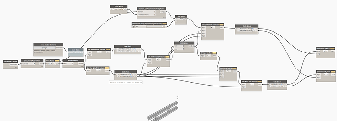
So I have been doing a bit more investigating but unfortunately cannot get this to create dimensions. I feel like I am 95% there but struggling to create references from the faces to dimension off. I have added a sample file, script file and the png for the script file. The script may be a bit long winded but I am looking to only dimension one of the start points of each unique face and then creating a dimension from those faces. I have also included a snapshot of the end result I am trying to achieve in case anybody knows of any quicker methods. I am aware that the families are not great quality and that is why I have to resort to dimensioning off faces. Unfortunately the project development is too far ahead to replace families. Any input is much appreciated. Thanks
Dimension Automation Sample.rvt (2.4 MB)
Dimension Automation.dyn (101.4 KB)
1 Like
Which view you want to make dimensions at?
Hi @Hyunu_Kim
In this case I am looking at creating the dimensions in the section or plan view. I assume the same methodology and script will create dimensions in assembly elevation views if I specify those views in a separate file.
Here is my approach.
The graph returns two dimensions. One is for the longest, the other is for all faces.
It runs in any plan, section, elevation, or Assemply views.
And you can easily add graph for side dimensions using it.
I thought that more universal graph would help not only you but also other members here.
All of python scripts are originaly written. And no packages necessary.
See attached.
Dimension Automation_EnjoyRevit.dyn (50.1 KB)
1 Like
Thank you @Hyunu_Kim, I have tested it and seems to be working beautifully.
I should be able to reverse engineer the script a bit to get the dimensions more specific to my requirements.
1 Like
Do I need to adjust the dimension to be in another direction?
I hope to annotate it in this direction of the Dimension.
Please help, thank you all.


