Seems like this thread is going in circles a bit… from what I can see Paul is seeking a vertex reference ultimately given the edges don’t seem available due to their orientation not being predictable in nature and able to support perpendicular dimension strings.
I played around with the code and explored references and encountered similar dead ends, as well as not being able to isolate endpoint references from curves/lines of an object successfully. Some API calls also didn’t seem to work as intended in Python, but might just be me (e.g. solids weren’t providing edge/face references to me). Searching the forum yields some similar dead ends or unsolved requests of this nature.
Might be worth seeing if @Alban_de_Chasteigner has some insight here as no doubt has explored this area of the API in Python extensively.
The API documentation isn’t clear on this - partially because the term ‘linear dimension’ is very loaded and inconsistent, and partially because automating dimensions is a painful task.
The most only solution I know of that allows you to keep the references straight is to utilize a planar edge reference - the specific implementation of which can vary significantly, be it a edge, face, model or detail line, reference plane, grid (what I was coming back to as the ‘floor’ statement elsewhere in the thread had me thinking plan), or something else entirely.
There is a good example of how one developer did this on the building coder blog (via the Revit API forum l) here: The Building Coder: Vertical Dimensioning and Revit API QAS Research
A user utilized that code to produce their desired outcome, illustrating the issue they were having beforehand here: Solved: Dimension created with API switches from linear to aligned - Autodesk Community
And good api sample can be found here: Solved: Re: Linear Dimension between two points (Revit 2018) - Autodesk Community
@Paul_Wintour I know none of these are direct solutions to the problem you face, but as I see it therer is a requirement to add a new element to the model in instances when a perpendicular reference was not given (even if temporarily so as some of these appear to be doing - not sure I trust that though) is likely a big part of the reason this hasn’t been done in a readily consumable package. I’m afraid it’s just a really limiting part of the API at the moment.
@jacob.small makes some valid recommendations; we’ve faced similar hurdles before (unselectable edges) and resorted to using detail lines as workaround. This was already a step our client was taking as they weren’t able to dimension certain edges or faces.
The start point of any API endeavour such as this should always begin with: can you achieve it manually? If not, then neither can the API, as illustrated above (bar a tiny amount of exceptions to this rule). So you might want to consider this as an alternative. Just remember it’s limited: if the element changes your dims wont follow as they’re not constrained to any element reference. Plus you’re adding new detail lines into your drawings.
Points are valid references since they’re selectable manually. To obtain them via the API, you have to use Edge.GetEndPointReference().
You can only obtain references from geometry derived directly from an element, e.g you can’t transform it, modify it or create say a point on an edge, and try and obtain a reference from it. @GavinNicholls your problem is either a violation of this rule or you haven’t set the Options.ComputeReferences flag to true.
The elephant in the room is your end goal: what exactly are you attempting to achieve? If this script is destined for use by an end-user and you resort to reference points, the user will have to use to trial and error to find the outermost edge indexes so your script can obtain the point references. If you want to be able to handle any geometry type, what if the outermost edges are non-linear? It’s potentially a minefield which will create a sour taste in the user’s mouth and wreck your hopes of improving their workflow. If on the other hand you implement an algorithm to search for the outermost edges this will restrict the function of your script to very particular usecases which may or may not be a good thing?
EDIT: Also, something else you might find useful re obtaining geometry from a reference so you can debug/check what type of geometry it is, you can use Element.GetGeometryObjectFromReference() then convert it to a Dynamo type. Catch here is, you need the originating element to make the call.
2 Likes
In the case I tried I took a floor, used get_Geometry to get its underlying Solid then attempted to query its faces or edges (also tried iterating over the Solid which one example I found strangely showed - don’t think a Solid is Python iterable though so discarded that idea pretty fast). Even with the Options tuned to compute references and work with nonvisible objects Edges and Faces weren’t available properties so there’s an extra step I missed I think.
From there my goal was to get the end point references of the found edges, but probably a missing step in my logic along the way or I used a method that wasn’t suitable for getting a workable solid in the API. Think get_geometry might get the dynamo geometry so might be the issue, will look into it furthet tomorrow.
Edit: No idea why it didnt work for me before, working code in next post. I’ll lay it down to a work computer being a work computer…
3 Likes
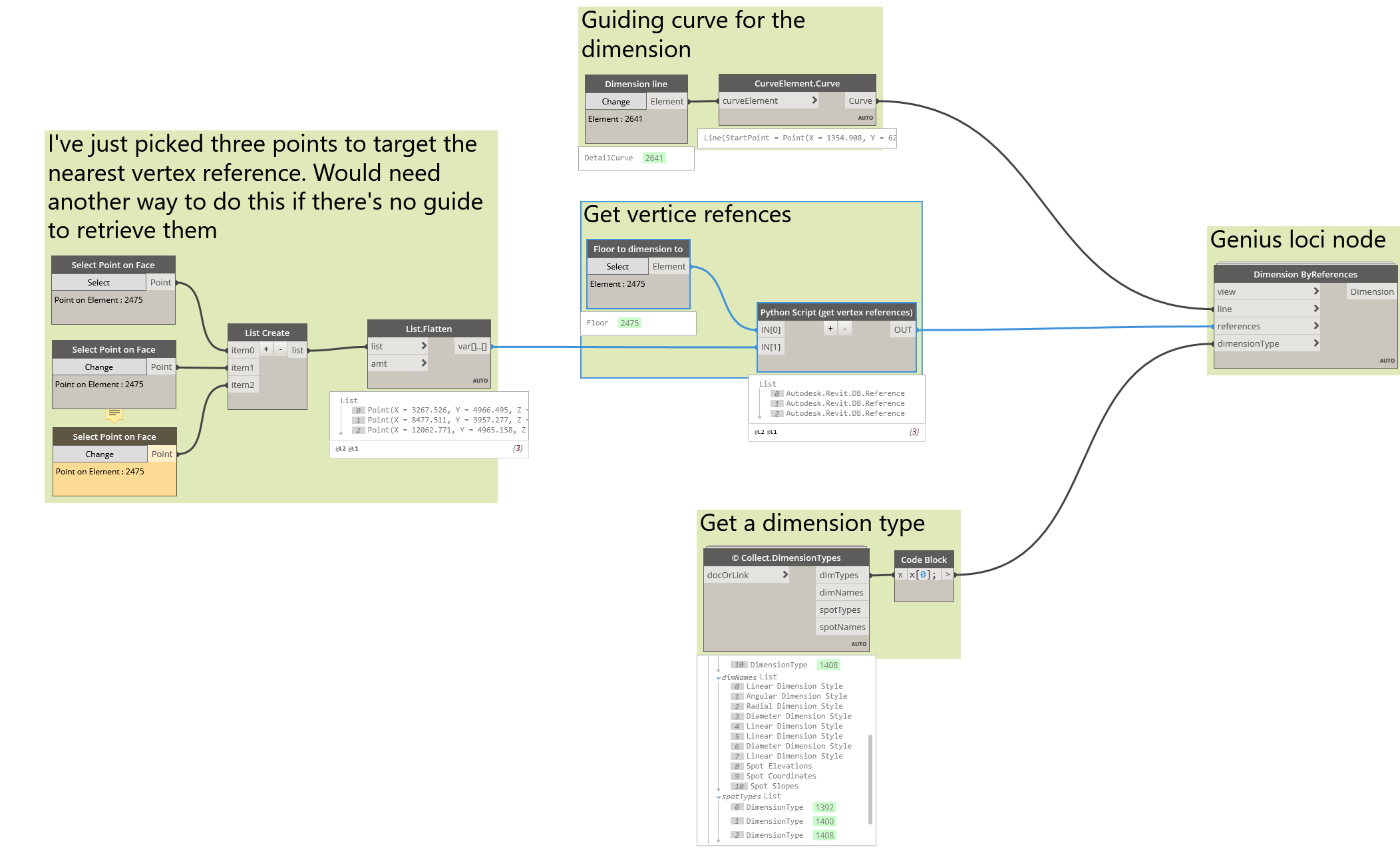
@Paul_Wintour not sure if vertices are a viable alternative, the thread got a bit sidetracked since the start of the conversation from edges/faces, but if you could retrieve the relevant vertice related to a desired edge or face closest to a location line to work around it maybe that’s another approach…
Retrieving vertices is awkward, in my test I’ve just got the end points and the corresponding references and grabbed the closest ones to some picked points in Dynamo.
# Made by Gavin Crump
# Free for use
# BIM Guru, www.bimguru.com.au

# Boilerplate text
import clr

clr.AddReference("RevitNodes")
import Revit
clr.ImportExtensions(Revit.GeometryConversion)

clr.AddReference("RevitAPI")
import Autodesk
from Autodesk.Revit.DB import *

# Preparing input from dynamo to revit
ele = UnwrapElement(IN[0])

opts = Options()
opts.ComputeReferences = True

# get floor edges
solids = ele.get_Geometry(opts)
edges   = [s.Edges for s in solids][0]

# get start and end points/refs
endrefs1 = [e.GetEndPointReference(0) for e in edges]
endrefs2 = [e.GetEndPointReference(1) for e in edges]
endpts1  = [e.AsCurve().GetEndPoint(0) for e in edges]
endpts2  = [e.AsCurve().GetEndPoint(0) for e in edges]

# combine to single lists
endrefs = endrefs1 + endrefs2
endpts = endpts1 + endpts2

# get closest ref to points
refPoints = UnwrapElement(IN[1])
getRefs = []

for p in refPoints:
	rvtPt  = p.ToXyz()
	dists  = [rvtPt.DistanceTo(ep) for ep in endpts]
	minDs  = min(dists)
	getRef = endrefs[dists.index(minDs)]
	getRefs.append(getRef)

# Preparing output to Dynamo
OUT = getRefs
try to vertex dim.dyn (23.7 KB)
@GavinNicholls thanks for looking into this. I tested your method but I think it has the same issue. The dimension is created as though it is LINEAR but as soon as you try to move it, it reverts back to an ALIGNED dimension. Does the same happen on your PC?
I can create a LINEAR dimension manually specifying the exact same verticies and the dimension works as expected. So I’m not asking Revit to do anything it can’t do already. Creating it via the API appears to work but switches to an ALIGNED dimension once you try to move it. But comparing the three options (manual, API before editing, API post editing) they all appear to be the same in Snoop. I’m not sure if this is the right field, but all the filed look the same.
I thought the issue could be resolved with using a vertex reference instead of an edge reference but it doesn’t looks like it makes any difference. @jacob.small did you have any luck following up with the Revit team?
@Thomas_Mahon there is no elephant in the room. I provided the minimum version of the problem as per guidelines. Geometry retrieval is all automated, completed and working. The only bug is when no perpendicular references exist. Hence my question about using edges and/or vertices as an option.
I believe it’s working for me in R22 as intended, although it remains at the dimension guide curve even if the object rotates. See below video to see if this is your intended outcome.
If it loses one of the mid references it loses propagation, but otherwise seems to hold true to diagonal type and also the guide line when moved or element is moved/rotated.
@GavinNicholls so I’ve only tested it with 2 points which explains the discrepancy. I need the overall, max dimension, so it must be 2 points.
The very fact that the references, base curve and dim type remain the same but the number of references affects the alignment of the dimension seems like a bug to me. Hoping @jacob.small or someone from the Revit team can explain if this is expected behaviour.
1 Like
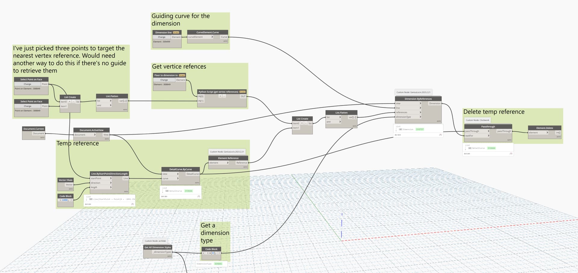
Feedback was to utilize the method shown in the forum post. It draws a temporary line to force a perpendicular edge, creates the dimension, then deletes the temporary line, and finally commits the transaction.
See the link here: Solved: Dimension created with API switches from linear to aligned - Autodesk Community
Have you tried that yet?
Thanks for this. I haven’t tried it yet. But my intuition says that creating a dimension to a detail line which is then deleted means that the dimension would no longer be associated to an element. It may remain linear, but would it be associative?
There really should be a better way to achieve this in the API.
Sorry - should have been clear by this bit. I’ll spell it out in a bit more detailed pseudo code steps as it’ll be a good long term reference.
- Get the reference of the points you want to dimension to as a list.
- Start a transaction.
- Draw a temporary line perpendicular to the direction you want the dimension to be - usually this will be one of the cardinal vectors as a line. You don’t need this long term - think of it as a dummy line.
- Get a reference to the line you just drew (let’s call it a dummy reference) and add that to the list of point references.
- Get the location line for where you want the dimension.
- Get the dimension type.
- Create the dimension from the type, list of references (now with an added dummy reference), and location curve.
- Delete the dummy line (which negates the reference but who cares, it was temp anyway).
- Commit the transaction.
As far as why this is needed, I have no clue. I can however hypothesize a possibility by reviewing the UI. If you observe the temp geometry you’ll see that when locating the dimension string you’ll you can generate both vertical and horizontal dimensions by manipulating the mouse. By reading the location of the mouse relative to the midpoint of the string Revit can quickly build a vector which can define a line which allows setting the display of the UI.
OK so I got this to work.
It is not the most elegant but it gets the job done. I’ve kept the create dimension node as-is (from Genius Loci). But I create a temporary detail line and add that as a reference. This forces a multi-segment dimension which is aligned correctly. Once created, the detail line is deleted and the dimension dynamically updated but most importantly, it keeps its orientation (even when manually moved). The dimension also remain associative, so if the element’s size changes, the dim will update.
The API logic still seems a bit absurb but it can work. Thanks for your help.
try to vertex dim.dyn (45.7 KB)
Dim check 2.rvt (1.6 MB)
6 Likes