I want to use column and framing line by cad,
Create multi outline to create floor.
But currently no idea how to proceed

@mansonchen , hi
here was a similar issue
Check out GeniusLoci Packages and BIMorph Nodes for getting inforamtion from .dwg
post your progress ![]()
KR
Andreas
Check out on boardtools …

Translated by admin. See below the line for original post.
Did you solve this problem please? I also encountered the same confusion, if you have solved it, can you share the result?
Original post below
请问您解决了这个问题吗?我也遇到同样的困惑,如果您已经解决了,可以分享一下成果吗?
Welcome to the forum!
The official language is english, which is a requirement to make search work. Please translate all future posts using your preferred online translation service as I did above.
Sorry, I will use English to ask or answer questions
I’m not 100% sure if dynamo has all the nodes to achieve this, but I do this in grasshopper using these steps:
- Get all curves
- Pull to XY plane
- Get their bounding box and section it with the XY plane (gives a surface)
- Split that surface using the lines (this is the step I’m unsure Dynamo has, feel free to correct me someone)
- Take the bounding box of each surface left
- Filter them out if they have a boundint width/depth that is smaller than a typical beam or column. This will give you most of the infills except for small excess ones if the DWG is clean
Hope that helps. Unfortunately there isnt a simple method as youre trying to detect space between objects rather than using objects themselves.
Hello, I tried for a long time or there is no way to achieve it, can you help me? It is best to upload a .dyn file
Only have enough time to share my workflow unfortunately, haven’t got a dyn for this as I don’t know if Dynamo is up to multi-split one surface by curves. Hopefully someone is able to assist further.
I had a quick try in both platforms and Dynamo gave me errors for splitting with many curves including duplicates, but I got it to work in Grasshopper so maybe the logic still helps. I’ve made a zip of the files here:

1 Like
Thank you, I hope someone can further test with Dynamo and succeed, look forward to it!

I wouldn’t recommend bounding boxes, as if your geometry is ever off axis you’ll have some issues. Instead utilize the maximum area of the split surfaces. It’s likely you could readily read the maximum beam length (column width/depth - grid spacing), and the widths are likely known as well. Length * width = beam area. Beams will always be larger than the columns area wise, and floors will be larger still. And so you can then get every surface larger than the maximum beam area would be an infill floor. The workflow would look something like this, but with a List.FilterByBoolmask node asking for areas over that beam area, instead of the sort/group by key nodes.

1 Like
In a real project, I had a new problem, which was when using BoundingBox.Geometry, and the result was not what I wanted. It generates a large rectangle, I just want to generate a graphic composed of outer outlines, can you help me solve this problem?

The only reliable method i can think of would be take the midpoint of the edges of each surface after the split, then find any with at least one edge that isnt very close to any of the actual lines used. If they are at the bounding box edge at least 1 of the surfaces edges wont be near a curve in your CAD file. That or drawn the outline manually.
1 Like
Thank you for the advice。
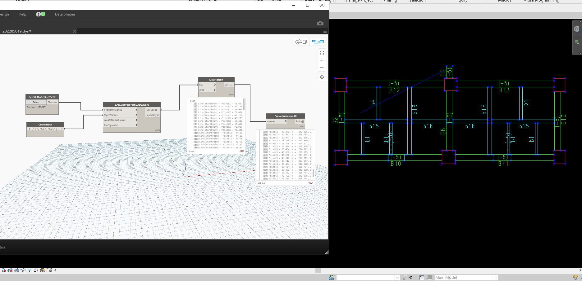
Hello, look at the side of Mr. Meychik’s process
Cordially
christian.stan
The geometry of the beams here looks more like walls then beams… Is this a ‘floor by room’ task rather then a ‘fill in between the beams’ task? I’d go a very different route if so.
I’d say this is a slab infill between beam/column grid. Comes up a fair bit on forums and in general user groups. It’s partially a wicked problem as it depends on how clean the input lines are, as well as catching heaps of fringe cases, sometimes the soft zones in structure can be quite small in one aspect when penetrations get involved, so it only really works when CAD is preliminary, which then leads to the question of why is this in CAD anyway.
The ‘door opening’ appearance in a few of the lines could be throwing me off? I suppose it could be a cleanliness of CAD data driving the issue just as well. Still comparing the sizes of the resulting shapes should provide meaningful output with the area method, as smaller elements would be discounted just as readily; the issue would be if the space between two beams was less than the width of a beam. All the same due to the sheer discrepancies in the data sets provided it’s likely that it’d be far faster to draw the beams in Revit rather than try and build the infill spaces, which would then make creating the infill spaces far easier as it’d be the spaces where there isn’t a solid created by the beam geometry.
1 Like
@mansonchen Hi , Could you help me I have the same problem. And I want to solve it with dynamo
update your dyn and rvt ~
1 Like