Hi everyone,
I am trying to create a Ramp Clearance Height check in Dynamo. I am using the floor surface as a base and making extrusions in a certain direction. However, when I use Geometry.Intersect to check the overlap of two solids, but the result I get is a surface instead of a solid. Could anyone advise me on this? Thanks in advance!
Hi Raymond, welcome ![]()
Is there a chance the two solids have coplanar surfaces? (They touch, but don’t ‘intersect’)
What happens if you change the height?

another approach which I’ve used is as follows:
(it is easier than it sounds)
- create a grid of points on a z plane, at a suitable spacing (say 100x100mm)
- project these points onto one surface (top of ramp) & get the z values
(x=0, y=0, z=z1a; x=100, y=100, z=z1b etc) - project these points onto the other surface (soffit of roof) & get the z values
(x=0, y=0, z=z2a; x=100, y=100, z=z2b etc) - calculate the difference in z values for each xy value
- from this, you could generate labels for the points, showing vertical clearance at that position
- this approach has the benefit of showing where the clearance is a problem, or where it is getting close, rather than a yes/no for the whole thing
It seems you are working in Revit- but Civil3D has a built in function to compare surfaces like this & will generate, point labels, heatmaps or other visuals
The reason I don’t recommend this method is that it it’s easy to miss obstructions such as a light fixture, pipe, sprinkler head, etc.
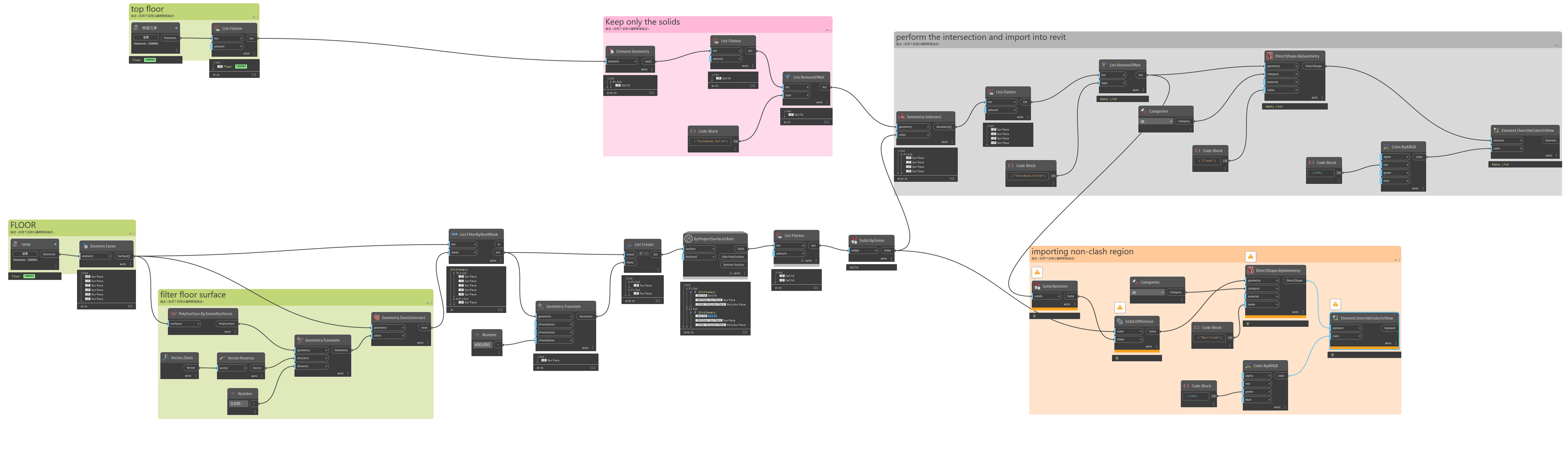
My method is as follows:
- Get all the floors, stairs, and ramps
- Extract the surfaces (Element.Faces)
- Filter out any surface which doesn’t have a normal at parameter 0.5,0.5 with a Z component over 0.5 units.
- Copy the surfaces vertically by [0, clearanceHeight] to get pairs of each surface, one directly above the other.
- Extract the perimeter curves of each and join into curve loops
- Loft each curve loops into a solid for each face (note you may have to handle openings if you have donut shaped ones)
- Union the solids into one
- Send the resulting solid as geometry on a new subcategory to the Dynamo environment as a new “floor clearance” family and create an instance thereof.
The resulting family instance can then be updated (leverage element binding or build new families) and used for clash detection in Navisworks, Revit’s own InterferanceChecker, ACC Moodel Coordiantion, or used in Dynamo as subsequent “element intersects element” selections.
Haha, we’re in different time zones. I’ll try again tomorrow, but I did try vertically copying the surfaces at the start point and the end point, and then connecting them with Solid.ByLoft. However, the result was still empty.
true, but that also applies to the solids-based approach, depending what is selected in the first place, plus you’ve got overlapping solids which can be difficult to interpret
My experience is a sampled points approach is simpler than generating new solids (something always goes wrong- loops, unexpected geometry etc)
Plus once you’ve got the pairs of points you can do something with them- like insert an adaptive family as a virtual version of the old fashioned ‘height pole’