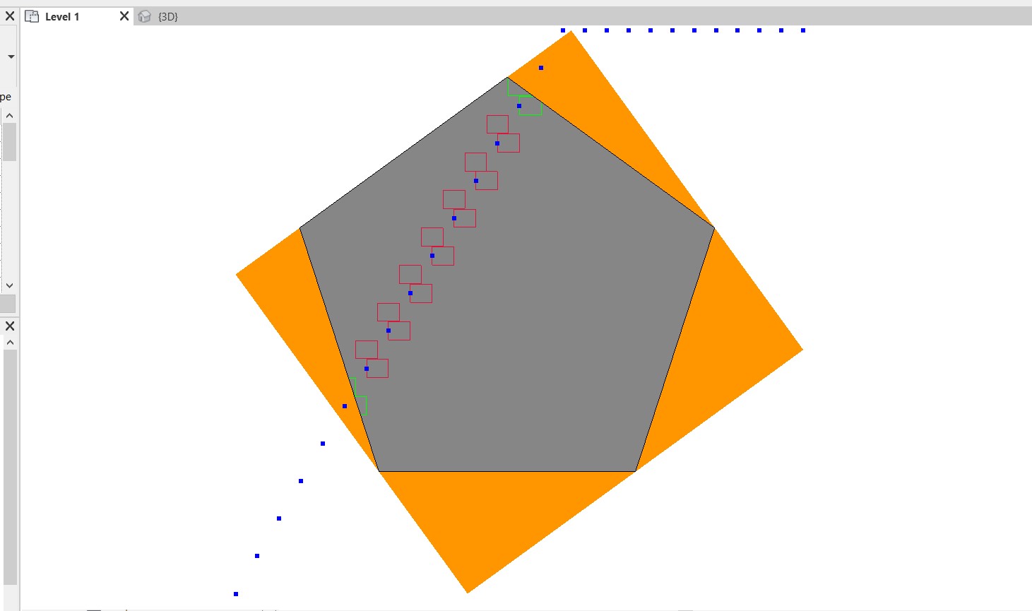
Orange is the bounding box, Grey is the floor, any node I can use to align and rotate the bounding box with the selected edge (red line) on floor? Thank you.

Below is the result I want that I did manually.
You’ll need to transform the geometry to align with the Coordinate System, Create the Bounding Box and then transform back the Bounding Box geometry to its original position
In the example below the floor edge (to which the BB needs to be aligned) and floor are selected
Got stuck on aligning the tiles (399 cuboid) with the selected edges.
I tried to use the Geometry.Transform but warning is shown. Any idea? Attached the dyn file for your quick reference.
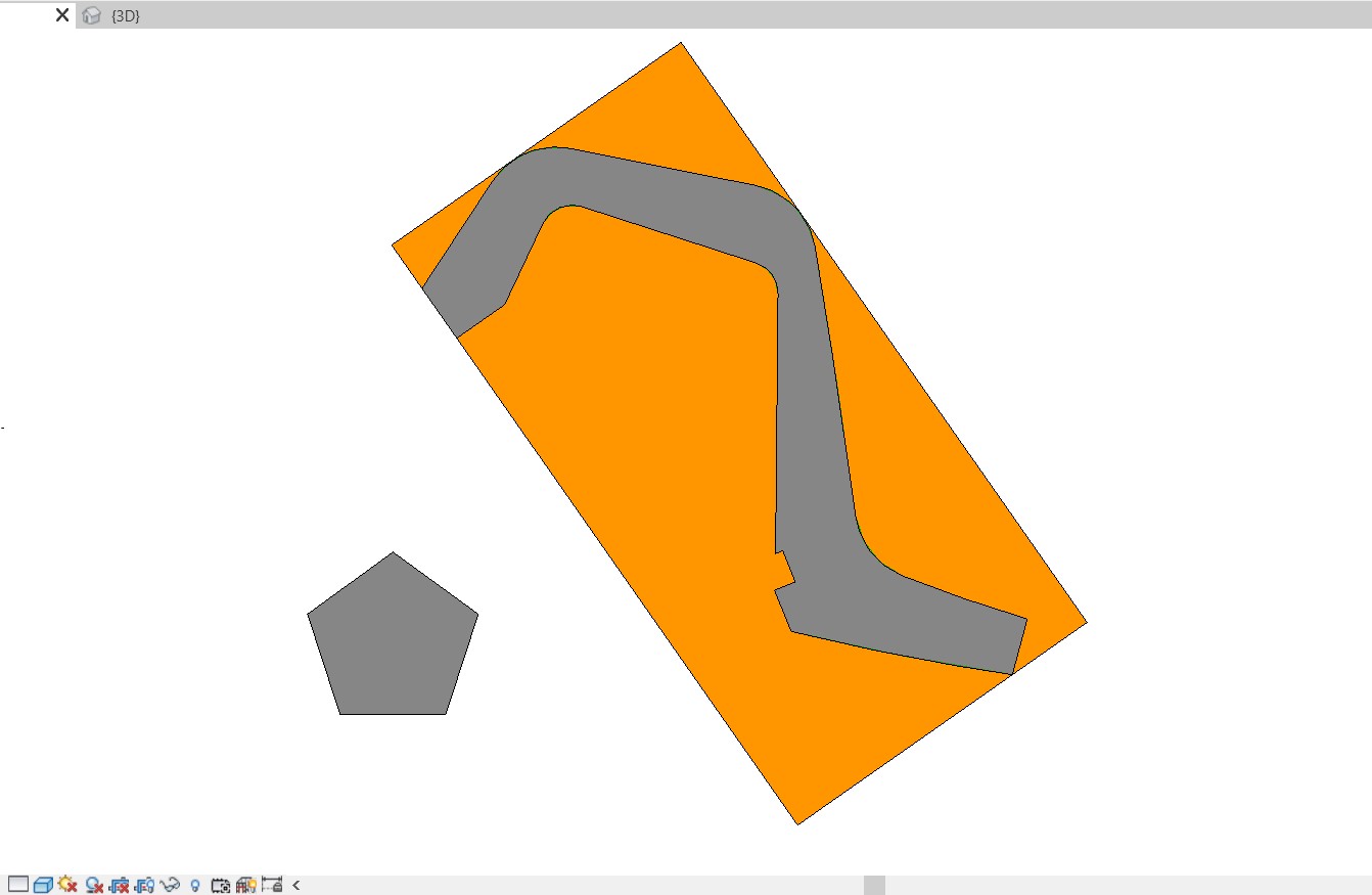
Thanks Vikram, but this created another bounding box rather than the original one, I tried to apply your script with my original bounding box (it created a new light orange bounding box under the polygon floor), is there a way to translate the existing tiles?
If the objective is to get the number of tiles (cut,uncut and total), you should be able to obtain that information from the graph provided without attempting to incorporate it into another graph.
You’ll need to just get the count of the lists from the last FilterByBoolMaskNode (in and out should give you cut and uncut)
You’ll need to create the tiles after the first transform (not earlier) and then transform it to the original floor orientation.That way the alignment is also transformed, not just the position.
Is it possible to align a BoundingBox to a Family ? For example in Grasshopper a bounding box automatically aligns / best-fit to a 3d object.
I have windows on different walls, and I need BB on each window aligned to the respective wall ? is it possible ?
In Revit API, bounding boxes cannot be rotated, because they are aligned with the world coordinate system.
Regards,
And how can it be aligned to a geometery ?
Hello @hassan.orion as @Organon say it isnt possible… you can convert to cuboid or curves and play around with that…or take your geometry from your elements as will follow your coordinate system…
hey, Jpeele, you aligning method worked. its just that the aligning works by rotating it by keeping the main object as center point, hence throwing away the object far away. I am trying to add re-center the object.
If you’re driving a Buick down the aisle at the local stop and shop, the capability of The transportation method might not be the problem, but rather the way you address it.
Dynamo (and quite a few other applications) returns the axis aligned bounding box in all cases. The arbitrarily oriented bounding box (what you are describing) is much slower to compute, and in my experience doesn’t provide enough benefit to offset the impact on speed. An object oriented bounding box (what has been described in this thread) does have uses but requires a degree of sophistication to build up in the Dynamo environment. More info here if you’re interested: Minimum bounding box - Wikipedia
Because of the speed impact, rather than examining how to build any of the above, can you indicate why you need the non AABB?
It may be that in the case of your windows I’ll assume you are looking for insight into the removed mass on the solid wall, perhaps for energy analysis. Rather than bounding boxes, I suggest working with the width, height, wall depth, and the window’s total transform to get what you need. All of those are mathematical properties, or require a trivial constructor (cuboid by length width height) for each family type, a scaling of the coordinate system returned by the window’s location, and then applying the scales coordinate system acordingly.
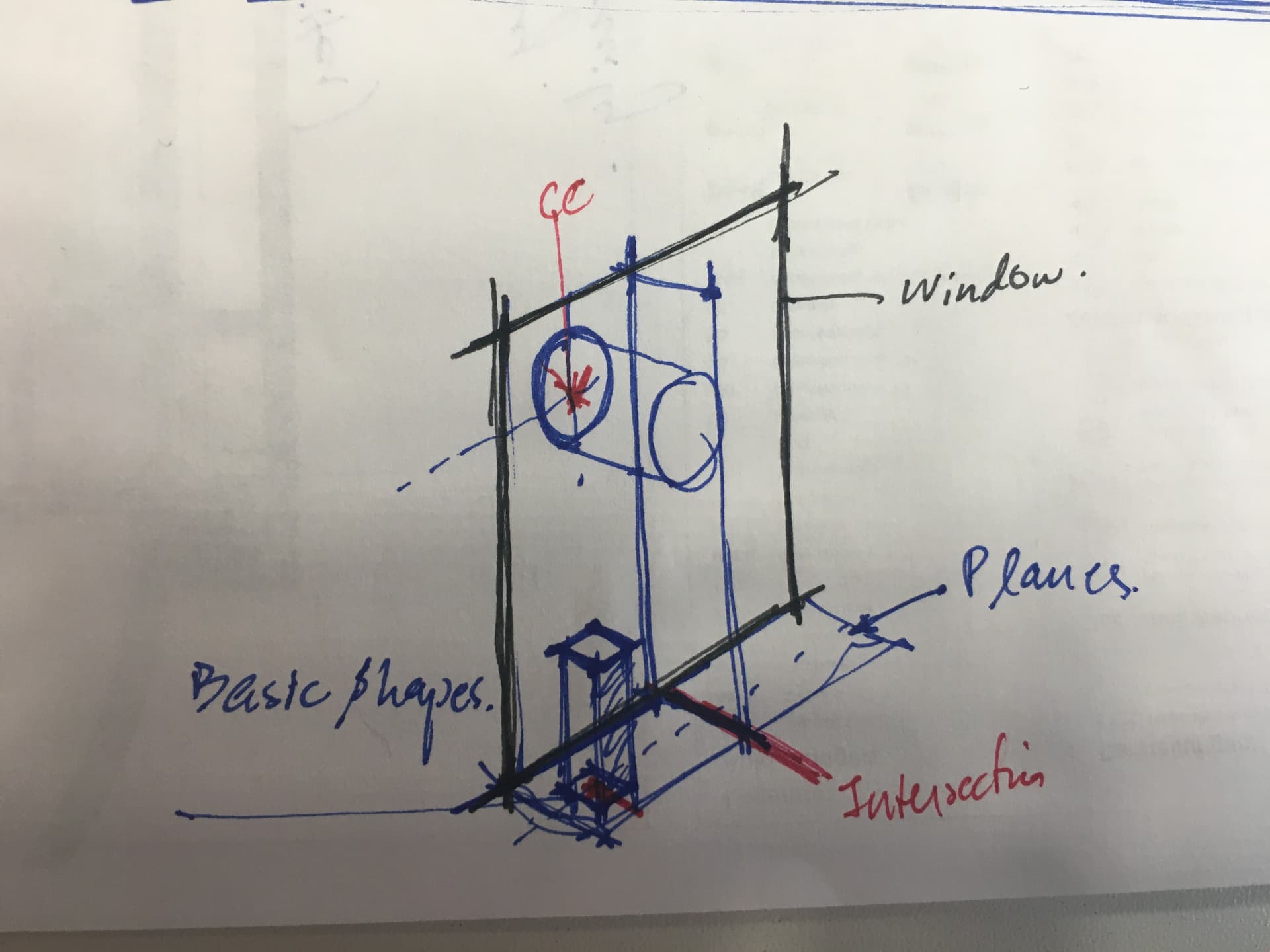
@ JacobSmall, I was trying to add some geometry to the window . ( Though I solved it with nested families later ). I just thought I could solved it with planes and basic shapes.
I can explain my initial working here :
I have windows on various planes of the houses. ( Houses aren’t following any orthogonal grids )
I wanted to extract three principal planes from the aligned BB, of each window ( blue planes in picture ), and then work form there on-wards by offsetting planes, intersecting them, get curves, makes shapes, extrude. That was the thought process, but I got stuck with just the planes.
I have done that in Grasshopper before. I had a very basic script that I can run over any solid element, and add customised desired-shape.
This can be achieved through nested families in Revit, I just thought if it is doable through Dynamo.
Back to the question, in grasshopper if you plug ‘extract plane’ to any shape, it gives you plane aligned to that geometry, very basic, one node. I was looking for something like that in dynamo.
Would be glad if there is something like that in Dynamo
That plane would likely be the derivative XY plane of the family’s transform (local coordinate system). This would clued the location, an X, Y and Z (normal) direction, giving you what you need to build new firm, or reorient the base geometry and then build new form.
and how may I extract the local coordinate system of the family / Instances ?
I believe there is a node for this in Archi-lab, but I may have my packages wrong. Check there first (make sure you install the right one - the forum has a few topics in that front). I’ll confirm on my lunch break.
If you transform geometry then the inverse transform will put it back to the starting location
In dynamo ‘Bounding Boxes’ are not boxes. They are just two points in space representing the min point and max point of a world aligned box. It is a different structure than how grasshopper represents them. Dynamo Bboxes are more set up for collision/proximity detection than for geometric calculation.