Set CropBox of 3D view

I am trying to set the crop box (not section box) of a 3D view so that it is as compact as possible, i.e. based on the bounding box.

The ‘View.SetCropBox’ node requires a bounding box, but if the bounding box of the geometry is used, the view is cropped incorrectly.

I am assuming the problem has something to do with the view angle and different coordinate systems but I haven’t been able to figure out how to generate the correctly orientated bounding box.

Any suggestions?

@c.poupin I think did a post on his blog about this, looks like exactly what you are after.

Python Script from Cyril Poupin
import clr
import sys
import System
from System.Collections.Generic import List
clr.AddReference('ProtoGeometry')
from Autodesk.DesignScript.Geometry import *
import Autodesk.DesignScript.Geometry as DS

#import Revit API
clr.AddReference('RevitAPI')
import Autodesk
from Autodesk.Revit.DB import *
import Autodesk.Revit.DB as DB

#import transactionManager and DocumentManager (RevitServices is specific to Dynamo)
clr.AddReference('RevitServices')
import RevitServices
from RevitServices.Persistence import DocumentManager
from RevitServices.Transactions import TransactionManager
doc = DocumentManager.Instance.CurrentDBDocument

def get_Global_Middle(all_bbx):
    """
    Calculates and returns the middle point of a collection of bounding boxes.
    """
    minX = min([bbx.Min.X for bbx in all_bbx])
    minY = min([bbx.Min.Y for bbx in all_bbx])
    minZ = min([bbx.Min.Z for bbx in all_bbx])
    
    maxX = max([bbx.Max.X for bbx in all_bbx])
    maxY = max([bbx.Max.Y for bbx in all_bbx])
    maxZ = max([bbx.Max.Z for bbx in all_bbx])
    
    return XYZ((minX + maxX) / 2, (minY + maxY) / 2, (minZ + maxZ) / 2 )

# Create a filter Predicate to select elements for processing
filterCatModel = System.Predicate[System.Object](lambda x: x.Category is not None and
                                                     x.Category.CategoryType == CategoryType.Model and 
                                                     x.OwnerViewId == ElementId.InvalidElementId and
                                                     x.get_BoundingBox(None) is not None )

# Create a filter to exclude certain built-in categories
builtInCat = List[BuiltInCategory]([BuiltInCategory.OST_Cameras, BuiltInCategory.OST_SectionBox])
not_filterCat = ElementMulticategoryFilter(builtInCat, True)

# Collect elements using the filters
lstElems = List[DB.Element](FilteredElementCollector(doc, doc.ActiveView.Id).WherePasses(not_filterCat).ToElements()).FindAll(filterCatModel)

# Get the active view and define margins
view = doc.ActiveView
margin = 1  # in feet
margin_anot = 0.01  # in feet

lstTfPts = []
lstBBx = []

# Start a transaction to modify the document
TransactionManager.Instance.EnsureInTransaction(doc)

# Transform the bounding box coordinates
tfView = view.CropBox.Transform.Inverse
for elem in lstElems:
    bbxElemB = elem.get_BoundingBox(view)
    if bbxElemB is not None:
        lstBBx.append(bbxElemB)
        pt1 = tfView.OfPoint(bbxElemB.Min)
        pt2 = tfView.OfPoint(bbxElemB.Max)
        pt3 = tfView.OfPoint(XYZ(bbxElemB.Min.X, bbxElemB.Max.Y, 0))
        pt4 = tfView.OfPoint(XYZ(bbxElemB.Max.X, bbxElemB.Min.Y, 0))
        lstTfPts.extend([pt1, pt2, pt3, pt4])

# Calculate minimum and maximum coordinates from transformed points
minX = min(lstTfPts, key=lambda p: p.X).X
minY = min(lstTfPts, key=lambda p: p.Y).Y
maxX = max(lstTfPts, key=lambda p: p.X).X
maxY = max(lstTfPts, key=lambda p: p.Y).Y

# Define a new transformation
t = Transform.Identity
t.Origin = get_Global_Middle(lstBBx)
t.BasisX = tfView.BasisX
t.BasisY = tfView.BasisY
t.BasisZ = tfView.BasisZ

# Define a new bounding box
newBox = BoundingBoxXYZ()
newBox.Enabled = True
newBox.Min = XYZ(minX - margin, minY - margin, -10000)
newBox.Max = XYZ(maxX + margin, maxY + margin, -0.10)
newBox.Transform = t
view.CropBox = newBox

# Adjust crop margins
crop_shap_manag = view.GetCropRegionShapeManager()
crop_shap_manag.LeftAnnotationCropOffset = margin_anot
crop_shap_manag.RightAnnotationCropOffset = margin_anot
crop_shap_manag.BottomAnnotationCropOffset = margin_anot
crop_shap_manag.TopAnnotationCropOffset = margin_anot

# Complete the transaction
TransactionManager.Instance.TransactionTaskDone()

# Return the list of processed elements
OUT = lstElems
3 Likes

It gets pretty close but it is not accurate in some orientations.

It still isn’t clear to me what the orientation of the bounding box (in 3D) needs to be.

Anyone? @solamour @jacob.small any thoughts?

Hey,

BBs are axis aligned… Would your building be rotated at all?

That’s the only way I can find to break it :slight_smile:

Hope that helps,

Mark

image

Can you post a simple model with a view cropped as you want, and a view cropped as you’d want, and no other views in the document? My guess is there is a dataset issue not accounted for in the work which @c.poupin posted.

2 Likes

Here you go @jacob.small

3 views saved which are incorrectly cropped. My guess is that the bounding box is being orientated/roated and the origin is not quite right.

214_Crop box.rvt (1.6 MB)
214_Crop box.dyn (7.9 KB)

This is the way I’ve tried to do it:

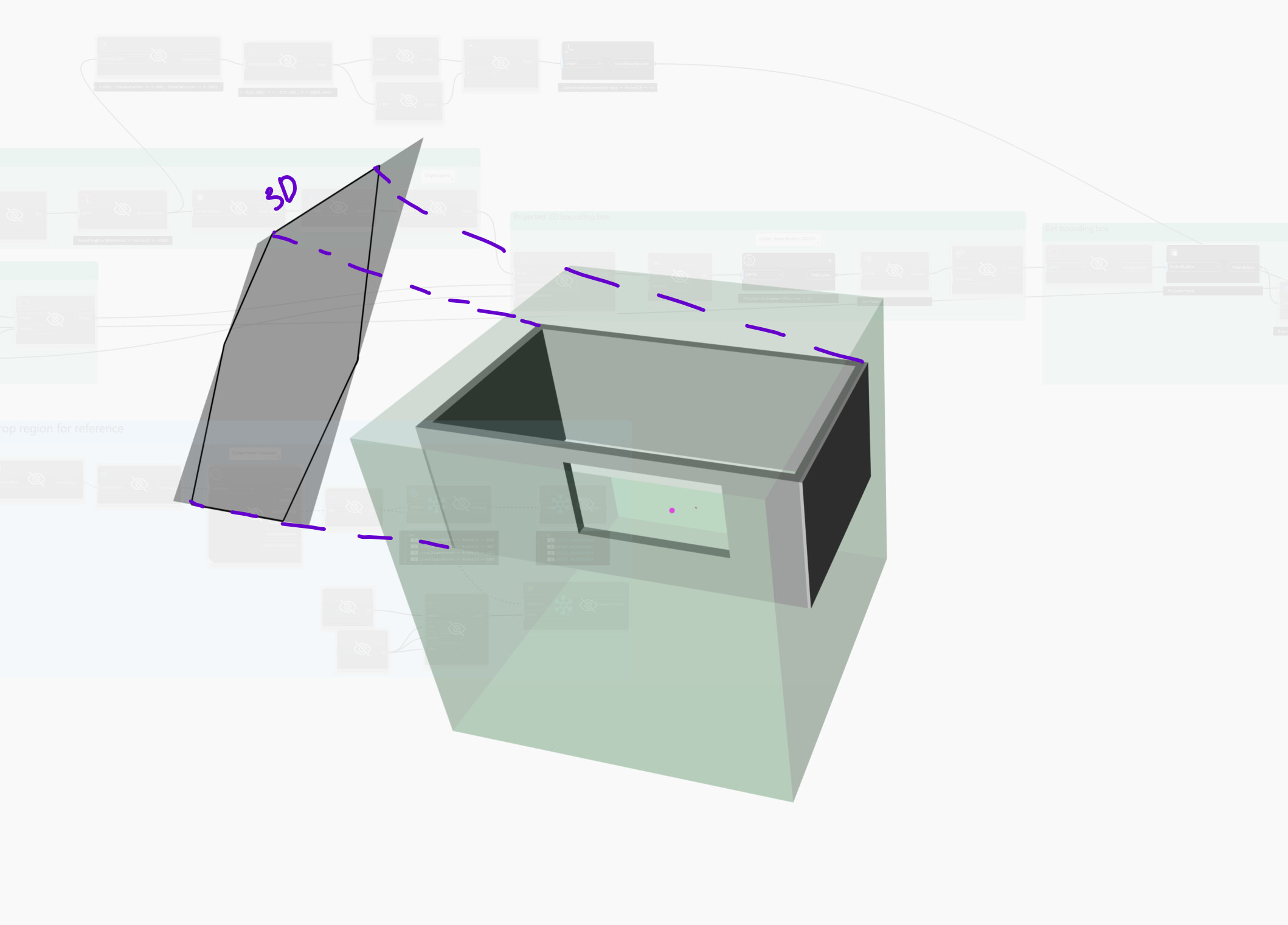
Get bounding box of geometry
Extract verticies
Project verticies to 3D view plan
Create convex hull
Create surface from curves
Get bounding box of surface -
Map bounding box to original bounding box coordinate system.

It is not quite there as I’m not 100% sure which orientation is needed. Also, even if the bounding box is the correct size, the position must be exact but where/how should it be placed?

214_Crop box_Dynamo.dyn (94.7 KB)

Hi @Paul_Wintour ,

here is the fixed code (thanks for the feedback)


import clr
import sys
import System
from System.Collections.Generic import List
clr.AddReference('ProtoGeometry')
from Autodesk.DesignScript.Geometry import *
import Autodesk.DesignScript.Geometry as DS

#import Revit API
clr.AddReference('RevitAPI')
import Autodesk
from Autodesk.Revit.DB import *
import Autodesk.Revit.DB as DB

#import transactionManager and DocumentManager (RevitServices is specific to Dynamo)
clr.AddReference('RevitServices')
import RevitServices
from RevitServices.Persistence import DocumentManager
from RevitServices.Transactions import TransactionManager
doc = DocumentManager.Instance.CurrentDBDocument

def get_Global_Middle(all_bbx):
    """
    Calculates and returns the middle point of a collection of bounding boxes.
    """
    minX = min([bbx.Min.X for bbx in all_bbx])
    minY = min([bbx.Min.Y for bbx in all_bbx])
    minZ = min([bbx.Min.Z for bbx in all_bbx])
    
    maxX = max([bbx.Max.X for bbx in all_bbx])
    maxY = max([bbx.Max.Y for bbx in all_bbx])
    maxZ = max([bbx.Max.Z for bbx in all_bbx])
    
    return XYZ((minX + maxX) / 2, (minY + maxY) / 2, (minZ + maxZ) / 2 )

# Create a filter Predicate to select elements for processing
filterCatModel = System.Predicate[System.Object](lambda x: x.Category is not None and
                                                     x.Category.CategoryType == CategoryType.Model and 
                                                     x.OwnerViewId == ElementId.InvalidElementId and
                                                     x.get_BoundingBox(None) is not None )

# Create a filter to exclude certain built-in categories
builtInCat = List[BuiltInCategory]([BuiltInCategory.OST_Cameras, BuiltInCategory.OST_SectionBox])
not_filterCat = ElementMulticategoryFilter(builtInCat, True)

# Collect elements using the filters
lstElems = List[DB.Element](FilteredElementCollector(doc, doc.ActiveView.Id).WherePasses(not_filterCat).ToElements()).FindAll(filterCatModel)

# Get the active view and define margins
view = doc.ActiveView
margin = 1  # in feet
margin_anot = 0.01  # in feet

lstTfPts = []
lstBBx = []

# Start a transaction to modify the document
TransactionManager.Instance.EnsureInTransaction(doc)

# Transform the bounding box coordinates
tfView = view.CropBox.Transform.Inverse
for elem in lstElems:
    bbxElemB = elem.get_BoundingBox(view)
    if bbxElemB is not None:
        lstBBx.append(bbxElemB)
        pt1 = tfView.OfPoint(bbxElemB.Min)
        pt2 = tfView.OfPoint(XYZ(bbxElemB.Min.X, bbxElemB.Max.Y, bbxElemB.Min.Z))
        pt3 = tfView.OfPoint(XYZ(bbxElemB.Max.X, bbxElemB.Max.Y, bbxElemB.Min.Z))
        pt4 = tfView.OfPoint(XYZ(bbxElemB.Min.X, bbxElemB.Max.Y, bbxElemB.Min.Z))
        #
        pt5 = tfView.OfPoint(XYZ(bbxElemB.Min.X, bbxElemB.Min.Y, bbxElemB.Max.Z))
        pt6 = tfView.OfPoint(XYZ(bbxElemB.Max.X, bbxElemB.Min.Y, bbxElemB.Max.Z))
        pt7 = tfView.OfPoint(bbxElemB.Max)
        pt8 = tfView.OfPoint(XYZ(bbxElemB.Min.X, bbxElemB.Max.Y, bbxElemB.Max.Z))
        lstTfPts.extend([pt1, pt2, pt3, pt4, pt5, pt6, pt7, pt8])

# Calculate minimum and maximum coordinates from transformed points
minX = min(lstTfPts, key=lambda p: p.X).X
minY = min(lstTfPts, key=lambda p: p.Y).Y
maxX = max(lstTfPts, key=lambda p: p.X).X
maxY = max(lstTfPts, key=lambda p: p.Y).Y

# Define a new transformation
t = Transform.Identity
t.Origin = get_Global_Middle(lstBBx)
t.BasisX = tfView.BasisX
t.BasisY = tfView.BasisY
t.BasisZ = tfView.BasisZ

# Define a new bounding box
newBox = BoundingBoxXYZ()
newBox.Enabled = True
newBox.Min = XYZ(minX - margin, minY - margin, -10000)
newBox.Max = XYZ(maxX + margin, maxY + margin, -0.10)
newBox.Transform = t
view.CropBox = newBox

# Adjust crop margins
crop_shap_manag = view.GetCropRegionShapeManager()
crop_shap_manag.LeftAnnotationCropOffset = margin_anot
crop_shap_manag.RightAnnotationCropOffset = margin_anot
crop_shap_manag.BottomAnnotationCropOffset = margin_anot
crop_shap_manag.TopAnnotationCropOffset = margin_anot

# Complete the transaction
TransactionManager.Instance.TransactionTaskDone()

# Return the list of processed elements
OUT = lstElems

article blog updated

5 Likes

@c.poupin so that works.

So what am I doing wrong? I’ve changed the logic slightly but it is mostly the same:

  • Get (unioned) bounding box of geometry
  • Get coordinate system of bounding box
  • Get view’s coordinate system and then its inverse translation
  • Transform geometry’s bounding box
  • Recreate new axis aligned bounding box (with no margins)
  • Set crop box based on bounding box

But it is not quite right. I’ve tried three different options for the view’s coordinate system but it is not correct.

Any suggestions on how to resolve? @jacob.small

214_Crop box.rvt (1.6 MB)
214_Crop box_Dynamo_v2.dyn (74.2 KB)

1 Like

Anyone?

Sorry I must have missed this over the holiday rush.

Can you explain/show what is off about it now?

@jacob.small

My version isn’t working at all becuase I’m not sure of the logic. Using a simple geomtrically based bounding box (in world coordinates) with the set crop box, crops the view incorrectly. The bounding box needs to be transformed somehow and them possibly a new axis-aligned bounding box created from that.

I found this help document, which states that “the crop box is a parallelepiped” but Dynamo’s set crop box is based on a bounding box.

1 Like

I managed to get this to work. However, there might be a more elegant solution…

214_Crop box_Dynamo.dyn (83.2 KB)

1 Like

There is a lot of added ‘bounding box’ nodes here.

Transforming the geometry from the context coordinate system to the origin and pulling the bounding box of that, then transforming the bounding box to the context coordinate system is likely the best path in a pure Dynamo context. However as you likely guessed this would be rather time consuming as Dynamo isn’t going to want to move that many solids efficiently.

The Revit API method above uses this directly, although with the bounding box of the elements rather than the full geometry. I’m not sure I’d go that route as Incan see some potential trimming issues as the view rotates, but if it hasn’t been an issue for others yet then it’s likely good to go.