Actually first I tried with -1000 and 2000, then my solid becomes like a big column and the points are hidden inside and I couldn’t see it. Then I tried to just arbitrarily chnage those values. Still it is not helping.
Maybe because you have greater slopes in yours?
The principle is that you need a bigger + than -
Try -7 & + 20 
You could improve the script by using values which relate to the topo Z values…
Hope that’s helpful,
Mark
Yaa like my slope has a difference of 4m.
To improve the script I need a good knowledge and I have just started working on it.
I don’t know what to do.
I don’t know what to do.
Instead of +2, try +20? ![]()
It is always good to start simple… Once you’ve got something working, increase the complexity…


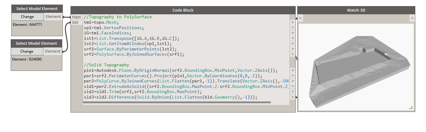
Great… How does the Watch 3D look?
Right now you are previewing everything there… both the big extrusion, and the final split surfaces, so it’s hard to see whether the split worked ok…

Is this what you wanted?
Here it connects actually.
Why does it show like a big chunk in the above image (in the preview window)?
1 Like
So the sequence you did above…
Create Solid
Split
Both of those steps are visible in the background.
So you plug a Watch 3D in and see the result only of your output.
If you were doing this with nodes, you would right click and ‘unPreview’ the bits you don’t want to see…

As a new user, it would be really useful for you to try and rebuild Vikram’s code using nodes… He is obviously an expert, for us mortals, reading code makes it more difficult to understand (part of the reason he has done it in code is to make it run faster).
2 Likes
You simple way of writing is really helpful for me to understand. Thankyou very much.
So that means the final result I will always have to look back on the Revit window after plugin the watch 3D node?
Yess I will try to rebuild “Vikram’s Code” using nodes.
1 Like
@lupamudrasharma.88 The second last line in the code block needs to be a little more specific
sld1 = per2.ExtrudeAsSolid(Vector.ZAxis(),(srf2.BoundingBox.MaxPoint.Z-srf2.BoundingBox.MinPoint.Z)+0.5);
Here is a file that works with your .txt file…
solidTopo.dyn (29.8 KB)
Topographylage.txt (4.3 KB)

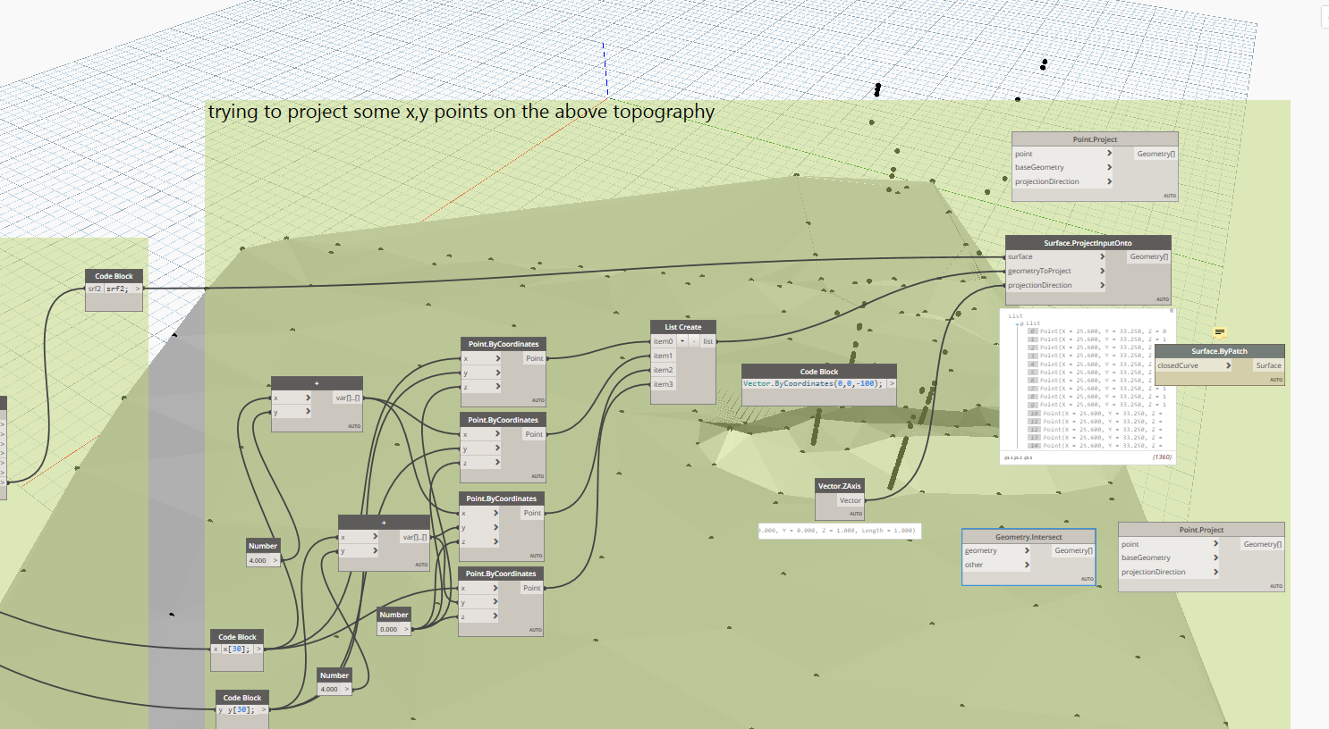
I want to ask another question:
How can I choose from the list of coordinate points a set of four coordinates say which will be my plot boundary (closed loop say a 2D plane if I do not choose the z). Then that boundary I extend it to touch the topography, so that I can evaluate the 4 values of z

I am choosing 4 coordinates randomly now and trying to project that 2D plane to touch the topography below. Eventually i need the values of z. Ultimately I want to know cutting/filling of the depth to build a house in a hilly terrain.
maybe draw a vector/line downwards and see where it intersects the topo?
how to get the boundary points of this topography? So that I can have a perimeter and finally work ahead with it.
Can someone shed some light on it.
Can somebody tell me what I am doing wrong with this?
I want to project a 2D plane (representing the base of a building) to the topography as I want the z values?

I have just put z=10 otherwise the plane is created down.
BUt after putting z=0 and then then trying to project that plane onto the existing topography and giving the direction of z, I am not able to see anything.

Thank you in advance


Hi, I Have been trying Vikrams script, but seem to be getting an error, not sure what to do… Ive uploaded a screenshot.

Would be helpful if you could provide (upload here or provide link if uploaded elsewhere) relevant dyn and rvt (small and purged) files
Meanwhile, delete the last line from the code to first first check if the solid topography is created.
Ive tried deleting the last line, still get an error.
For this definition to work you’ll need to delete the Building Pads and Create a Mass representing the extents of the building

topoSolid.dyn (11.6 KB)
Thank you Vikram for taking your time to look at this for me, I really appreciate it!
Okay, so I have created the mass and deleted the pads, used the script you attached, but I now am getting an error stating “Asked to convert non convertible types”
A mass does appear in the backround, but its a flat mass and nothing appears in watch 3d.

Ive uploaded the files below