deepening of the path of M. @Draxl_Andreas to be precise ![]()
Thnks, Cristian!
Just for your information also check next option - sometimes Holes for detail has a different rotation or different count of segments (depend on family what makes holes). In this case we cant use any methods of compare distances between centroid and Vertexes.
In my script its also didnt work – different BestFitPlanes positions. But How you can see on next video
assembly algorithm determinate same geometry (I think it based on principle Solid.Difference as told @Daan [thanks for Idea!] above == Null if the same) - see next pic

Question is - how to place this 2 geometry in one location!? No have an Idea ![]()
With pleasure invite the Guru to the discussion @GavinNicholls, please
2 Likes
These days I tend to use more abstract approaches for this that are less accurate but more memory friendly. My current method I use in Grasshopper is to get the bounding box min/max points, the volume and the faces count and convert them to a combined string.
From there indices if duplicates can be found. Now of course it ignores a lot of aspects such as shapes which have the same bb, volume and face count but the chance of this is quite unlikely unless your model is quite generic in nature (e.g. all cubes). Given this known level of likelihood, I find it is usually safe to use.
If you’re trying to analyze same geometry independent of the location in xyz space then use the bb width/depth/height instead as they are spatially independent.
1 Like
i think you should look at this node
cordially
christian.stan
BB dont help - its always use a global CS. We have to find a way to determinate a local CS for every element

The question remains open - how is this implemented in the system assembly algorithm
I use it but better version Node[Geom, FromCS , ToCS]
1 Like
I think @GavinNicholls has a tutorial on his Youtube channel showing how to fit bounding boxes to geometry objects.
@y.Petrenko please provide me with a sample Revit file so I can give it another go.
1 Like
Ah yes if you need to include rotation and don’t have any means of assessing that rotation (e.g. a family orientation) then you’ll be in for a world of hurt on this one I’d say. Maybe a cumulative sum of the edge lengths and the volume? Highly unlikely a duplicate form would yield a match unless it was a true duplicate.
1 Like
I don’t think a sum would work entirely because some of the objects he is working with have the same edge lengths, just in different positions in the solid.
I think working out the distances between the edges and the centroid if the solids might be the way to go.
1 Like
Yes potentially. A distance matrix would be more accurate for sure, just might be conputationally intense I guess.
Such a method should be chosen based on the sample size of the model and the level of likelihood that the method would return incorrect results.
1 Like
In the model if you try to make an Assembly for every part - its Identify its as the same.
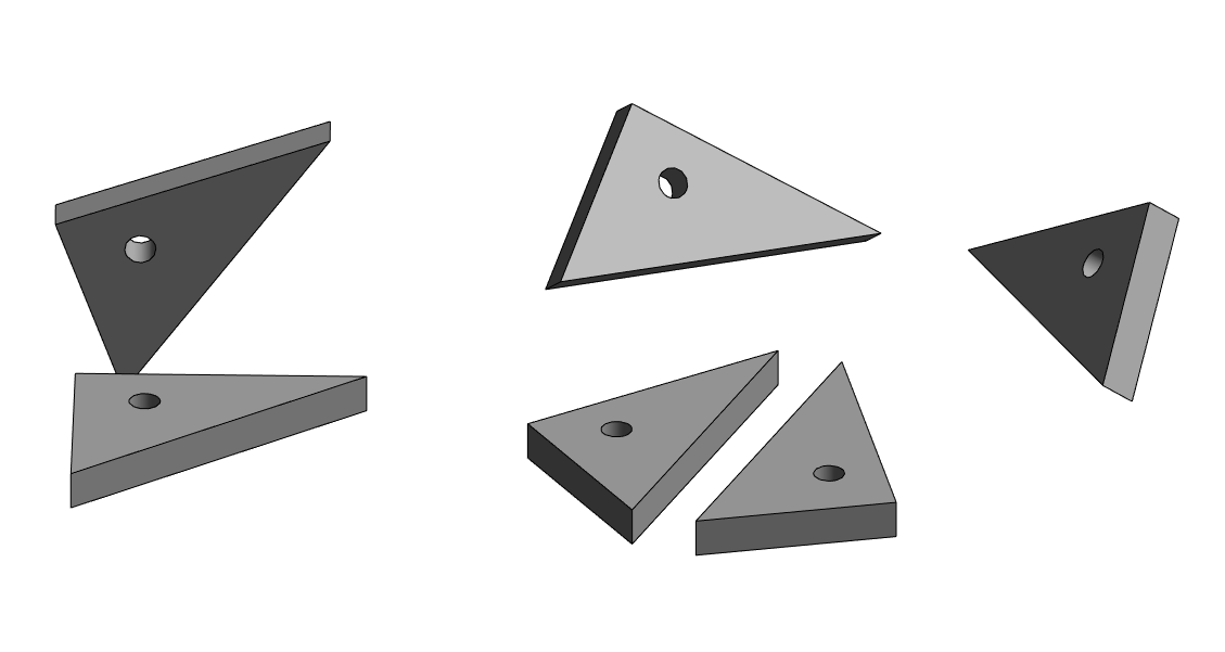
But be aware - that some of them has a different count of Surfaces

As result you have to find a way how to get Null of Solid,Difference node == means geometries are the same (just use a Deconstruct.List methode for first and rest compare)
Have fun! and Thanks
Assembly Engine of Identify.rvt (504 KB)
Here you go!
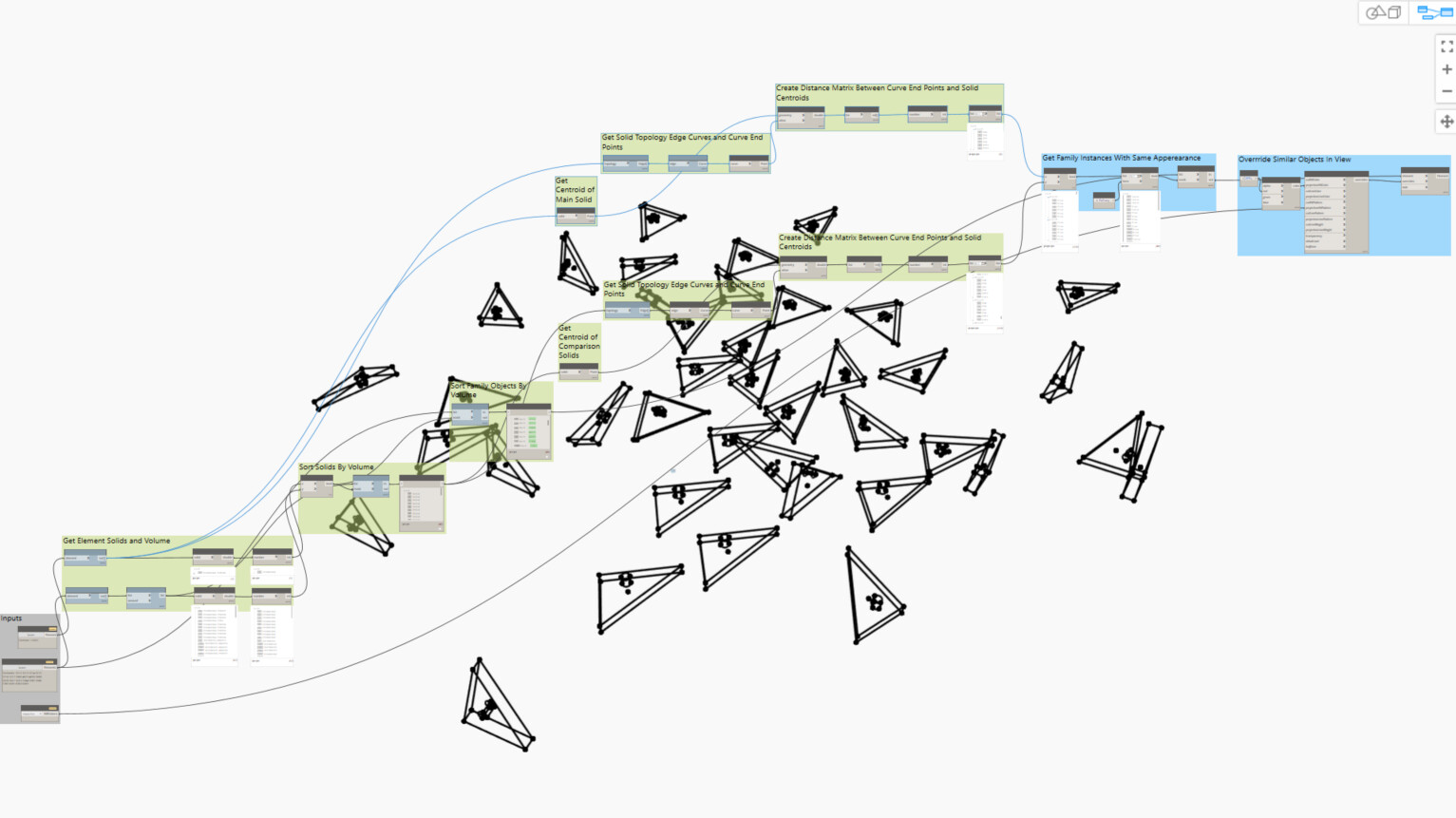
I think it works well now. It should work for any condition. I altered the previous graph I made to create a distance matrix between the solid centroids and edge curve endpoints instead of a family origin. It is a shorter graph, so runtimes should be smaller. All done using OOTB nodes.
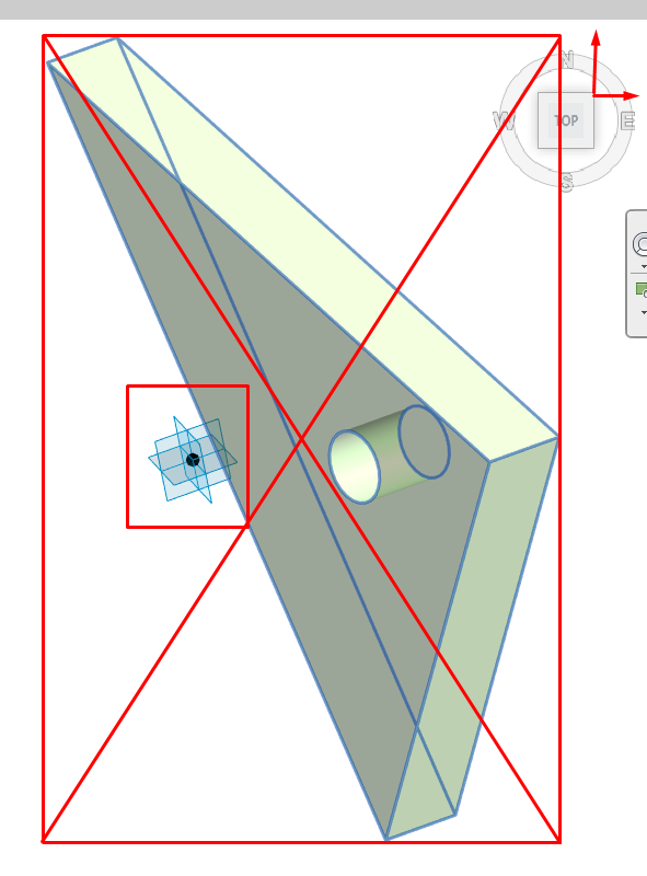
However, you must make sure that the cut out shapes you draw have the same sketch outlines. In your Revit model, I noticed that one of the circles has a split outline.
See the dynamo file attached.
Cheers.
Filter Solids_Rev2.dyn (81.9 KB)

Thanks for your efforts!
When I start work on this task I made it as well.
But here is really interesting thing - that Assembly Creator didnt see a different if some surface has a different sketch outlines == different count of surface/vertex/edges.
its compare geometry totally. And for my opinion we can make it only if place both geometries in one location and get a Solid.Difference. That is only way.
About Assembly creator, lets think together about it:
- You create a first(Parent) instance. Inside of Assembly we get an IdentifyOrigin Element (system)

its like a system assembly CordinateSystem (CS) and place it for Parent Instance on the center BottomFace of BB.
2. When we create a second(Child) instance what has a different rotation, position and count of Surfaces - Assembly compare it (Some kind of mystic) and puts the Origin for this assembly in an identical place with reference to geometry but not with reference to BB
Question is - how, how, how? how we can get universal method for determinate origin CS between if we have a different count of Surface for 2 exactly same elements.
I apologize if I bored anyone with this topic. But I think this topic is very interesting and perhaps has a rather high level of complexity. ![]()
Assuming all solids are extrusions, here is an alternative
by analyzing the largest face then serializing solids object (for comparison)
import sys
import clr
import random
clr.AddReference('ProtoGeometry')
from Autodesk.DesignScript.Geometry import *

class SolidsUtils:
	lst_solid = []
	def __init__(self, solid):
		self.DS_solid = solid
		self.__class__.lst_solid.append(self)
		self.DS_computePoint = []


	def __repr__(self):
		centroid = self.DS_solid.Centroid()
		volume = self.DS_solid.Volume
		# get the max face
		max_face = max(self.DS_solid.Faces, key = lambda f : f.SurfaceGeometry().Area)
		curves = max_face.SurfaceGeometry().PerimeterCurves()
		# get all point
		# Arcs -> center point
		# other curves -> Start and End point
		pts_on_max_face = []
		for c in curves:
			if isinstance(c, Arc):
				endsPoint = [c.CenterPoint]
			else:
				endsPoint = [getattr(c, typePoint) for typePoint in ['StartPoint', 'EndPoint']]
			for pta in endsPoint:
				if all(pta.DistanceTo(p) > 0.01 for p in pts_on_max_face ):
					pts_on_max_face.append(pta)
		# remove points on 2 aligned curves
		self.DS_computePoint = []
		for p in pts_on_max_face:
			tempNormal = []
			for c in curves:
				if c.DistanceTo(p) < 0.01:
					tempNormal.append(c.NormalAtParameter(0.5))
			if len(tempNormal) == 2 and tempNormal[0].Cross(tempNormal[1]).Length < 0.01:
				pass
			else:
				self.DS_computePoint.append(p)
		# compute sum of Vectors: centroid -> points on surface
		sum_vector = Vector.ByCoordinates(0,0,0)
		for p in self.DS_computePoint:
			v =  Vector.ByTwoPoints(centroid, p)
			sum_vector = sum_vector.Add(v)
		sum_Vertices_Vector = sum_vector.Length
		return "Solid_Repr(Volume = {0:.4f}, Sum_Vertices_Vector = {1:.4f})".format(volume, sum_Vertices_Vector)

	def __eq__(self, other):
		return repr(self) == repr(other)

	@classmethod
	def CountSolid(cls):
		dictCount = {}
		for obj in cls.lst_solid:
			if repr(obj) not in dictCount:
				dictCount[repr(obj)] = [obj.DS_solid]
			else:
				dictCount[repr(obj)].append(obj.DS_solid)
		return dictCount

	@classmethod
	def GetAllComputePoints(cls):
		return [obj.DS_computePoint for obj in cls.lst_solid]

input_Solid = IN[0]

for s in input_Solid:
	o = SolidsUtils(s)
	print(repr(o))
result = SolidsUtils.CountSolid().items()
OUT = result, SolidsUtils.GetAllComputePoints()
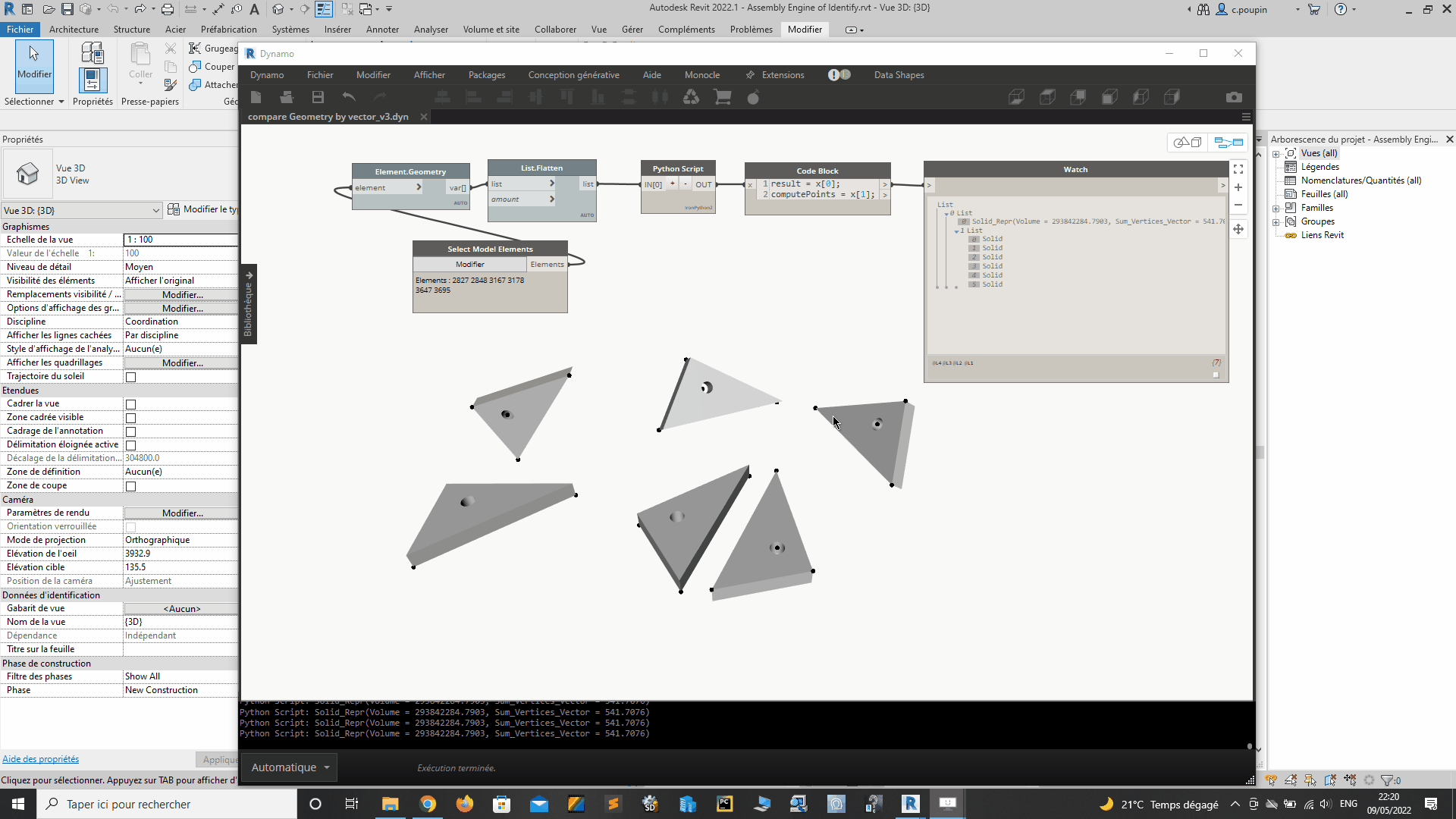
compare Geometry by vector_v3.dyn (13.1 KB)
4 Likes
OMG! You are my hero!
it remains only to understand how it works
I’ll sit and take apart the pieces
I will try to repeat this with the help of nodes, for a more visual understanding, or will it not work for me?
Thanks a lot! ![]()
Great code, but I see that checking as sum of Vector length is not enough ![]()

How we can double check this option for example?
Assembly Engine of Identify.rvt (644 KB)
An idea would be to use the origin of the face UV(0,0), but sometimes for an identical face this point can be different (depending on the direction of the edges)
1 Like
A variant,
for more complex geometries, it will probably be necessary to find a better algorithm

import sys
import clr
clr.AddReference('ProtoGeometry')
from Autodesk.DesignScript.Geometry import *

class SolidsUtils:
	lst_solid = []
	def __init__(self, solid):
		self.DS_solid = solid
		self.__class__.lst_solid.append(self)
		self._computePoint = []

	@property
	def DS_computePoint(self):
		""" get all point on largest Face with loops"""
		if len(self._computePoint) > 0:
			return self._computePoint
		#get the max face with loops and points on edges or centerpoints
		max_face = max(self.DS_solid.Faces , key = lambda f : (len(f.Loops), f.SurfaceGeometry().Area))
		curves = max_face.SurfaceGeometry().PerimeterCurves()
		pts_on_max_face = []
		for c in curves:
			endsPoints = [c.CenterPoint] if isinstance(c, Arc) else [getattr(c, tp) for tp in ['StartPoint', 'EndPoint']]
			for pta in endsPoints:
				if all(pta.DistanceTo(p) > 0.01 for p in pts_on_max_face ):
					pts_on_max_face.append(pta)
		# delete points located on 2 aligned curves
		self._computePoint = []
		for p in pts_on_max_face:
			tempNormal = []
			for c in curves:
				if c.DistanceTo(p) < 0.01:
					tempNormal.append(c.NormalAtParameter(0.5))
			if len(tempNormal) == 2 and tempNormal[0].Cross(tempNormal[1]).Length < 0.01:
				pass
			else:
				self._computePoint.append(p)
		return self._computePoint

	@property
	def Sum_Vector_fromCentroid(self):
		""" compute sum of Vectors: centroid -> points on surface """
		centroid = self.DS_solid.Centroid()
		sum_vector = Vector.ByCoordinates(0,0,0)
		for p in self.DS_computePoint:
			v =  Vector.ByTwoPoints(centroid, p)
			sum_vector = sum_vector.Add(v)
		sum_Vector_fromCentroid = sum_vector.Length
		return sum_Vector_fromCentroid

	@property
	def Cross_distace_pt(self):
		""" compute global distance between points """
		cross_distace_pt = 0.0
		for i in self.DS_computePoint:
			for j in self.DS_computePoint:
				cross_distace_pt += i.DistanceTo(j)
		return cross_distace_pt

	def __repr__(self):
		volume = self.DS_solid.Volume
		return "Solid_Repr(Volume = {0:.3f}, Sum_Vector_fromCentroid = {1:.3f}, Cross_Distance_Points = {2:.3f})".format(volume, self.Sum_Vector_fromCentroid, self.Cross_distace_pt)

	def __eq__(self, other):
		return repr(self) == repr(other)

	@classmethod
	def CountSolid(cls):
		dictCount = {}
		for obj in cls.lst_solid:
			if repr(obj) not in dictCount:
				dictCount[repr(obj)] = [obj.DS_solid]
			else:
				dictCount[repr(obj)].append(obj.DS_solid)
		return dictCount

	@classmethod
	def GetAllComputePoints(cls):
		return [obj.DS_computePoint for obj in cls.lst_solid]

input_Solid = IN[0]

for s in input_Solid:
	o = SolidsUtils(s)
result = SolidsUtils.CountSolid().items()
OUT = result, SolidsUtils.GetAllComputePoints()
compare Geometry by vector_v5.dyn (15.8 KB)
7 Likes
Hi @c.poupin
Sorry for jumping into thread as i seen pointless opening new one as this is highly related to what im trying to achieve.
Would there be a possibility to add list management to your current script?
Its works very well but i would like to introduce extra layer of grouping.
Say i want to group all solids together by material and run script in each sub list as some solids may be same but do have different materials and i would like to separate it.
Regards